





The Pressure Drop You Calculated Is Not the Pressure That Damages Your Valve
When engineers size a control valve for liquid service, they typically focus on the pressure drop between inlet and outlet — P₁ minus P₂. That number drives the Cv calculation, it goes into the data sheet, and it looks right on paper.
But the pressure that actually damages a valve trim never appears in that equation. It happens inside the valve body, at a point where the fluid jet contracts to its minimum cross-section and the local pressure drops far below P₂. If that internal minimum pressure falls below the vapour pressure of the liquid, vapour bubbles form — and when they collapse, they do so with enough force to pit hardened metal surfaces, generate noise exceeding 110 dB, and destroy expensive trim within months of commissioning.
That internal minimum-pressure point has a name: the vena contracta. Understanding exactly what it is, where it forms, how deep the pressure falls, and how valve geometry controls it is not optional knowledge for anyone specifying or troubleshooting liquid-service control valves. This article covers all of it.
What Is Vena Contracta? The Physical Definition
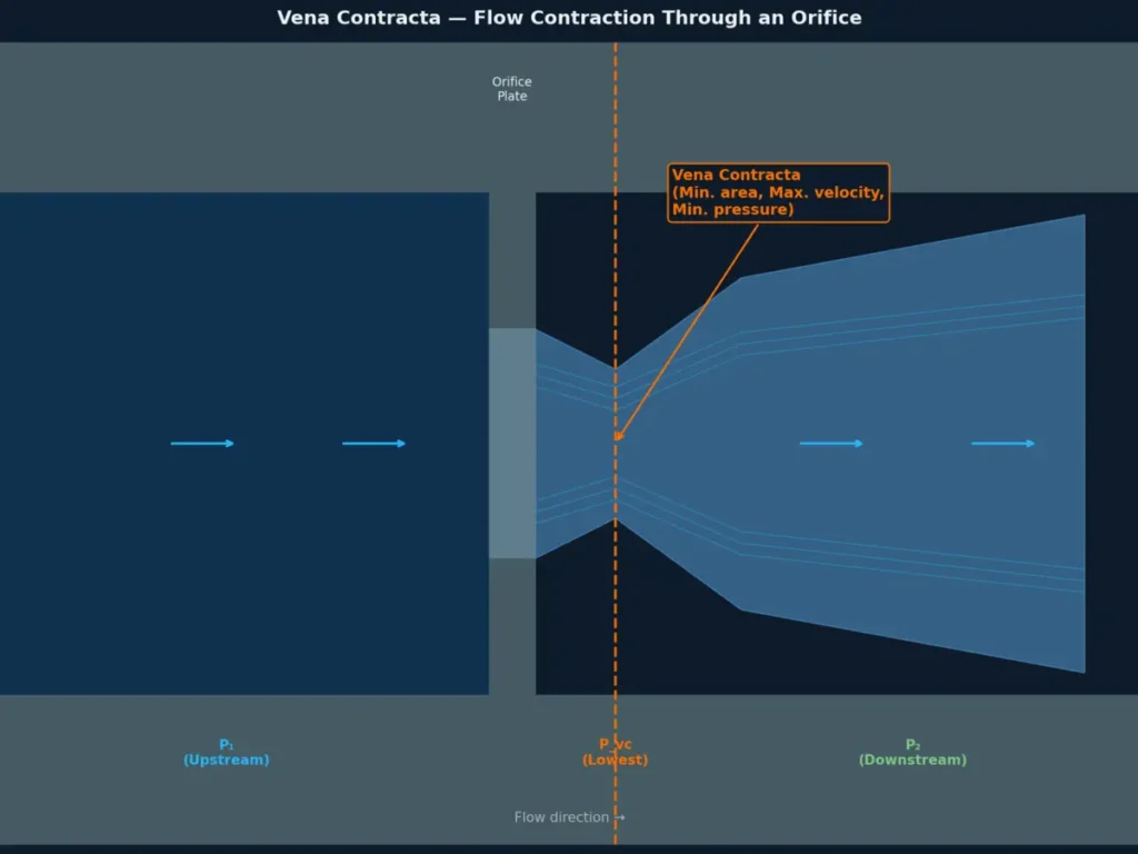
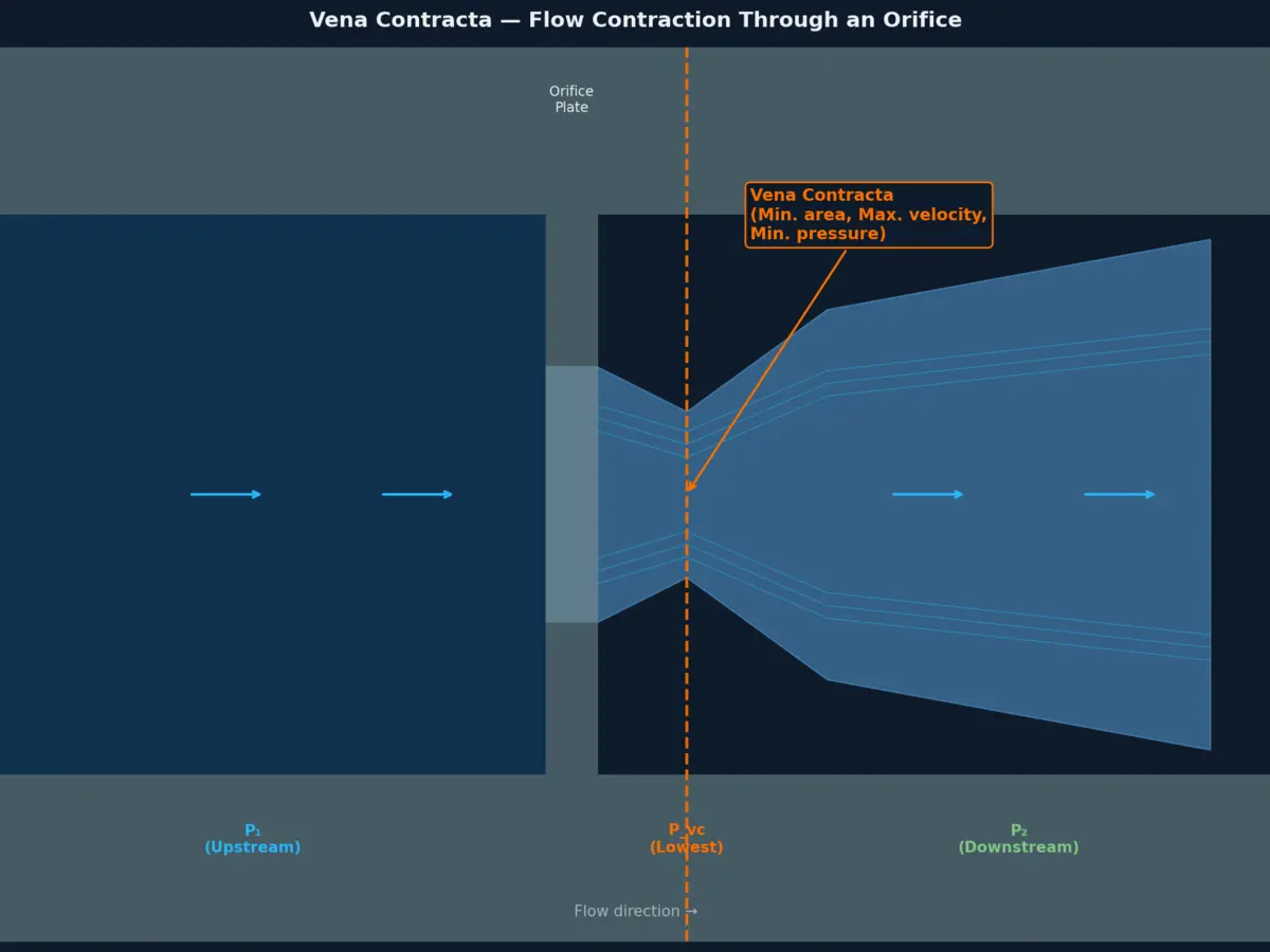
Vena contracta — Latin for "contracted vein" — is the cross-sectional point in a fluid jet where the flow area reaches its minimum, fluid velocity reaches its maximum, and static pressure reaches its lowest value.
The phenomenon was first described by Evangelista Torricelli in 1643 while studying flow from tank orifices. His key observation: when fluid issues from a sharp-edged opening, the jet continues to narrow for a short distance downstream of the opening before it begins to expand again. The narrowest cross-section of that jet is the vena contracta.
The physical reason is straightforward. Fluid streamlines cannot make sharp right-angle turns. As flow approaches a restriction — an orifice plate, a valve seat, the gap between a disc and seat ring — the outermost streamlines must curve inward gradually. That curving continues past the physical edge of the restriction, so the jet keeps contracting beyond the orifice itself. Only after the streamlines have fully turned does the jet begin to expand and the flow re-attach to the pipe wall.
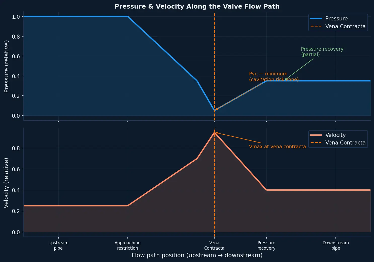
At the vena contracta, conservation of energy (Bernoulli's principle) governs the relationship between velocity and pressure:
- Flow area is at its minimum → flow velocity is at its maximum
- Velocity is maximum → static pressure is at its minimum
The ratio of the vena contracta cross-sectional area to the orifice area is called the coefficient of contraction (Cc). For a sharp-edged circular orifice under ideal conditions, the theoretical value of Cc is approximately 0.611 — meaning the jet contracts to roughly 61% of the orifice area at the vena contracta point.
Where Vena Contracta Forms Inside a Control Valve
In an industrial control valve, the vena contracta does not form at the valve seat itself. It forms slightly downstream of the seat, inside the valve body.
The exact location and severity depend on valve geometry:
Globe valves have a symmetrical plug-and-seat arrangement. Flow passes through a well-defined circular restriction, and the vena contracta forms in a predictable, compact zone just below the seat. This geometry is one reason globe valves tend to have higher pressure recovery factors — more on that below.
Rotary valves (butterfly, ball) have irregular cross-sectional flow areas that change continuously with disc or ball position. The flow restriction is asymmetric, particularly at partial opening, and the vena contracta can shift location as the valve throttles. At certain openings, localized regions of very low pressure can form before the overall flow path reaches its minimum — making rotary valves more prone to early-onset cavitation at lower pressure drops than a globe valve sized for the same Cv.
Cage-guided globe valves use multi-hole cages to divide the flow restriction into many small orifices, each forming its own vena contracta. By staging the pressure drop across multiple small restrictions rather than one large one, the minimum pressure at each individual vena contracta stays higher — which is the engineering rationale behind anti-cavitation multi-stage trim design.
Understanding which valve type is right for a given service begins with understanding how control valves work and what their trim geometry is designed to do.
The Pressure at the Vena Contracta: The FL Factor
The central engineering question for liquid-service valve sizing is: how low does the pressure actually fall at the vena contracta?
Valve manufacturers characterise this through a dimensionless valve-specific parameter called the Liquid Pressure Recovery Factor, FL.
FL is defined by the relationship:
P_vc = P₁ − (P₁ − P₂) / FL²
Where:
- P₁ = absolute upstream pressure
- P₂ = absolute downstream pressure
- P_vc = pressure at the vena contracta
- FL = liquid pressure recovery factor (valve-specific, published in manufacturer data)
The important insight from this equation: a lower FL value means the pressure at the vena contracta falls further below the upstream pressure for a given P₁–P₂ differential. Low-FL valves are inherently more prone to cavitation at the same pressure drop.
FL values vary significantly by valve type:
- Globe valves: FL ≈ 0.85–0.92 (high — pressure does not recover much past the seat; the vena contracta is severe but compact)
- High-performance butterfly valves (triple-offset / six-eccentric): FL ≈ 0.75–0.90 (dependent on disc geometry and opening angle)
- Standard double-eccentric butterfly valves: FL ≈ 0.55–0.70 (low — the vena contracta can produce substantially lower pressures for the same overall ΔP)
- Ball valves: FL ≈ 0.60–0.75 (varies strongly with trim style and opening percentage)
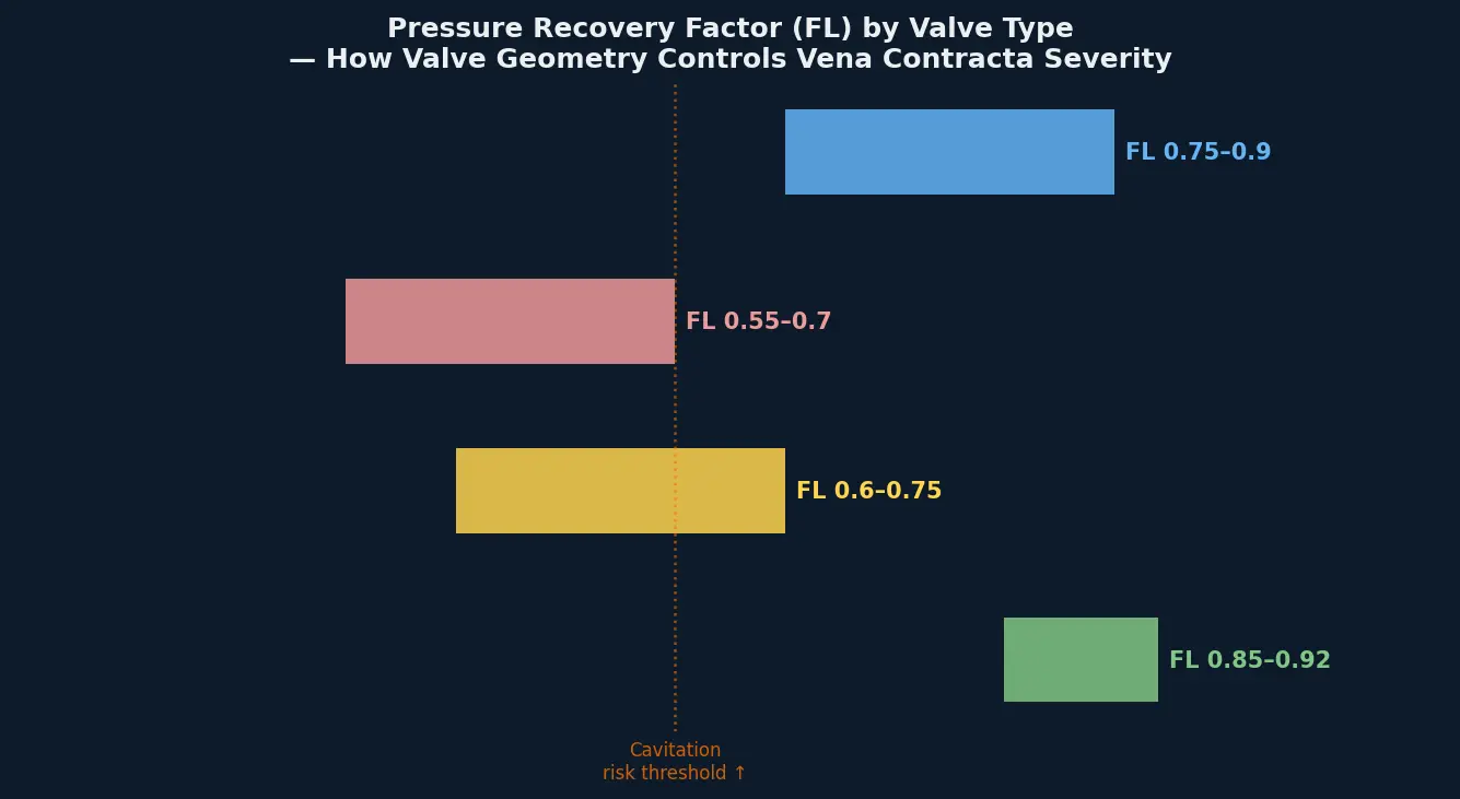
This is why two valves with identical Cv ratings can behave very differently in cavitating service. FL is not interchangeable across valve styles — it must be checked against process conditions at the sizing stage.
Vena Contracta and Cavitation: The Damage Mechanism
Cavitation begins at the vena contracta. When the local pressure P_vc falls below the vapour pressure of the liquid (Pv) at the flowing temperature, the liquid vaporises locally and vapour bubbles form in the jet.
Those bubbles are carried downstream with the flow. As the flow area expands past the vena contracta, pressure recovers. When the local pressure rises back above Pv, the bubbles collapse — rapidly and violently. Bubble collapse generates localised pressure spikes that have been measured in studies referenced by IEC 60534-8-2 at forces capable of producing micro-jet impact pressures high enough to pit hardened metal surfaces over repeated cycles.
The damage pattern is characteristic: pitting and cratering of seat faces, disc edges, cage walls, and downstream body surfaces — concentrated in the zone where bubble collapse occurs. Unlike flashing (where vapour remains in the downstream flow), cavitation involves the full collapse cycle occurring within the valve body, making it far more destructive to trim components.
For a detailed breakdown of how cavitation and flashing differ in their physics, damage patterns, and engineering countermeasures, see the Carter Valve guide to cavitation vs flashing in control valves.
When the Vena Contracta Drives Choked Flow
There is a second critical threshold beyond cavitation: choked flow.
Choked flow occurs when the vena contracta pressure reaches the vapour pressure of the liquid and a stable vapour phase forms in the jet. At this point, the flow rate stops increasing even if you continue to reduce downstream pressure. The valve is "choked" — it has hit its hydraulic ceiling for that set of upstream conditions.
This is the condition formalised in IEC 60534-2-1 and ISA-75.01.01, the international standards for control valve sizing. The choked flow pressure drop ΔP_choked is calculated using FL and the fluid vapour pressure:
ΔP_choked = FL² × (P₁ − FF × Pv)
Where FF is the liquid critical pressure ratio factor, approximately 0.96 − 0.28 × √(Pv/Pc), with Pc being the thermodynamic critical pressure of the fluid.
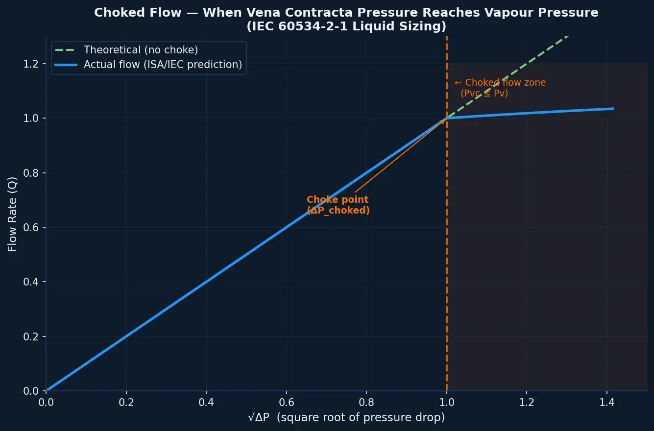
The practical consequence for engineers: if you size a valve using only P₁ − P₂ without checking whether the process conditions push ΔP past ΔP_choked, the valve will not deliver the predicted flow. It will cavitate, choke, and likely fail mechanically before it stabilises at the required operating point.
This is why the ANSI/FCI 70-2 and IEC 60534 leakage and sizing frameworks exist — to force the check of vena contracta conditions as a required step in valve selection, not an afterthought. Reviewing how control valve leakage classes and sizing standards work together is the logical next step after understanding vena contracta.
How Valve Design Controls Vena Contracta Severity
Valve engineers have several tools to limit the damage potential of the vena contracta in severe liquid service:
Multi-stage trim (staged pressure reduction) — Instead of dropping the full ΔP across one restriction, a multi-stage cage or series trim drops pressure incrementally across several stages. Each stage has its own vena contracta, but the local minimum pressure at each stage stays above Pv because each individual pressure drop is a fraction of the total. Anti-cavitation trim designs for globe valves use this principle directly.
High FL valve selection — For services where cavitation is predicted, selecting a valve geometry with a higher FL rating keeps P_vc further above Pv for the same P₁ and P₂. Globe valves are often specified over rotary valves specifically for this reason on high-ΔP liquid duties.
Hard-facing and erosion-resistant materials — Where the process conditions make cavitation unavoidable (for example, where flashing occurs regardless of valve design, or where cost constraints favour accepting some cavitation), the trim surfaces are protected with hardfacing alloys such as cobalt-chromium overlays. These extend service life by resisting the pitting mechanism rather than eliminating it.
Downstream velocity management — High exit velocities accelerate the erosive effect of cavitation bubble collapse on downstream piping. Sizing the valve with appropriate body size, using expanders, or routing flow to avoid impingement on pipe walls and welds reduces secondary damage downstream of the valve itself.
For isolation applications in severe service — where the concern is tight shutoff integrity rather than throttle control — Carter Valve's isolation valve range including triple-offset and six-eccentric butterfly platforms addresses the sealing challenges that arise when vena contracta-related erosion degrades seat surfaces over time.
Vena Contracta in Gas and Steam Service
While the term "vena contracta" most commonly appears in liquid-service discussions (where cavitation is the direct consequence), the same flow contraction phenomenon occurs in gas and steam service — with different but equally important consequences.
In compressible gas flow, the equivalent critical condition is sonic velocity at the vena contracta. When the gas velocity at the minimum-area point reaches Mach 1, the valve reaches its gas choke point and flow rate can no longer increase regardless of further reduction in downstream pressure. This condition also governs the onset of aerodynamic noise, as high-velocity gas jets interacting with lower-velocity downstream gas generate shock cells whose acoustic power scales sharply with vena contracta velocity.
In steam service, if vena contracta pressure falls below the saturation pressure at the flowing temperature, wet steam conditions can arise — with liquid droplet erosion becoming the dominant damage mechanism rather than cavitation per se.
The Carter Valve engineering and service team works through these condition-specific effects as part of valve selection for clients operating in oil and gas, LNG, FCCU, and power generation environments where multiple flow regimes may be present simultaneously.
Frequently Asked Questions
What is the difference between vena contracta and the valve seat? The valve seat is the physical sealing surface — the designed restriction in the flow path. The vena contracta is the hydrodynamic phenomenon that occurs downstream of that restriction, where streamlines continue to converge after passing the seat edge. The vena contracta is never co-located with the physical seat; it always forms slightly downstream of it inside the valve body.
Why does vena contracta matter for valve sizing if I already have the Cv? Cv captures the overall flow capacity of a valve at a given pressure drop. It does not tell you the local pressure conditions at the vena contracta. Two valves with identical Cv ratings but different FL factors will have dramatically different internal minimum pressures — and therefore different cavitation thresholds — for the same P₁, P₂, and fluid conditions. Cv alone is insufficient for liquid sizing when cavitation is a risk.
How is FL measured by valve manufacturers? Manufacturers determine FL by testing a valve at progressively increasing pressure drops until flow becomes fully choked — meaning further reduction in downstream pressure produces no additional flow. The FL value is then back-calculated from the IEC 60534-2-1 choked flow equation at the transition point between non-choked and choked conditions.
Can the vena contracta location be changed by design? To a degree, yes. Multi-stage trim designs effectively distribute the vena contracta across multiple smaller stages rather than concentrating it at a single point. Streamlined valve body geometries can reduce the severity of contraction. However, the phenomenon itself cannot be eliminated — it is a consequence of the conservation laws governing fluid mechanics. It can only be managed through geometry, staging, and material selection.
Does vena contracta affect isolation valves as well as control valves? Isolation valves are not normally throttled, so vena contracta effects during normal operation are minimal. The concern arises during controlled opening and closing, or if an isolation valve is ever partially cracked open for manual throttling — conditions that can produce cavitation damage to the seat face even in a valve not designed for throttle service. Valve leakage classes and their practical meaning in plant operation are covered in the guide to API 598, ANSI/FCI 70-2, and ISO 5208 leakage standards.
What noise levels can cavitation from vena contracta produce? In severe cases, hydrodynamic noise from cavitating control valves can exceed 110 dB at the pipe wall — well above OSHA occupational noise exposure limits for an 8-hour shift. IEC 60534-8-4 provides the standard methodology for predicting hydrodynamic noise levels from liquid control valves based on vena contracta conditions, mechanical stream power, and pipe wall transmission loss.
Request a Technical Consultation for Your Liquid Service Application
If you are specifying or troubleshooting a control valve in liquid service — particularly in high-ΔP, high-temperature, or two-phase conditions — understanding the vena contracta conditions in your specific duty is the right starting point.
Carter Valve's engineering team works through valve sizing, FL factor verification, and cavitation risk assessment for process conditions in oil and gas, LNG, chemical processing, and power generation. We support duty-specific valve selection and can provide FL data and sizing checks against IEC 60534-2-1 for applications where standard data-sheet sizing is not sufficient.
Tell us your service conditions — fluid, P₁, P₂, temperature, and flow rate — and we will recommend a configuration with the right trim geometry and material specification for your duty.
Request a Technical Consultation →
Explore our control valve range for severe liquid and gas service applications.
References
1. Torricelli, E. (1643) — Original description of vena contracta in orifice flow. Cited in: Wikipedia, Vena contracta — https://en.wikipedia.org/wiki/Vena_contracta 2. IEC 60534-2-1 — Industrial-process control valves — Flow capacity — Sizing equations for fluid flow under installed conditions — International Electrotechnical Commission 3. ISA-75.01.01 — Flow Equations for Sizing Control Valves — International Society of Automation 4. Jordan Valve — Pressure Recovery Factor Explained — https://www.jordanvalve.com/resource/pressure-recovery-factor-explained/ 5. Valin Corporation — Pressure at the Vena Contracta with Liquid Flow in a Control Valve — https://www.valin.com/resources/whitepapers/pressure-vena-contracta-liquid-flow-control-valve 6. Valin Corporation — Control Valve Liquid Flow: Choked Flow, Cavitation, Flashing — https://www.valin.com/resources/blog/control-valve-liquid-flow-choked-flow-cavitation-flashing 7. Emerson / Fisher — Understanding Choked Flow in Fisher Valves (product bulletin) — https://www.emerson.com/documents/automation/product-bulletin-understanding-choked-flow-in-fisher-valves-en-122950.pdf 8. Alicat Scientific — Avoiding Jetting in Mass Flow Controllers: The Vena Contracta — https://www.alicat.com/support/choosing-an-instrument-avoiding-jetting-in-mass-flow-controllers-the-vena-contracta/ 9. Williams Valve — The Cost of Cavitation: How Choked Flow Destroys Valve Internals — https://www.williamsvalve.com/blog/cost-of-cavitation-how-choked-flow-destroys-valve-internals/ 10. Piping Designer — Vena Contracta — https://www.piping-designer.com/index.php/properties/fluid-mechanics/2529-vena-contracta