


流動接触分解装置(FCCU)は、重質で高沸点の炭化水素留分を高オクタン価のガソリンやディーゼルなどの貴重な製品に変換する役割を担っており、近代的な石油精製所の心臓部と見なされることがよくあります。しかし、FCCUをこれほど収益性の高いものにしているプロセスそのものが、工業用バルブにとって最も過酷な環境のひとつを作り出しています。. FCCUにおけるバルブの侵食 サービスは、プロセス制御、プラントの安全性、そして全体的な収益性を脅かす広範な課題である。.
製油所では、しばしば 3 年から 5 年、あるいは 6 年へと延びる、より長いターンアラウンド間隔が求められており、重要な分離弁と制御弁の機械的完全性が最重要課題となっています。この記事では、触媒に起因するバルブの浸食のメカニズム、コンポーネントの故障がもたらす深刻な影響、そして特にトリプルオフセットバタフライバルブにおける高度なハードフェイスシート設計が、信頼性の高い FCCU の運転に不可欠である理由について説明します。.
FCCUの環境を理解する:なぜバルブは過酷な条件に直面するのか
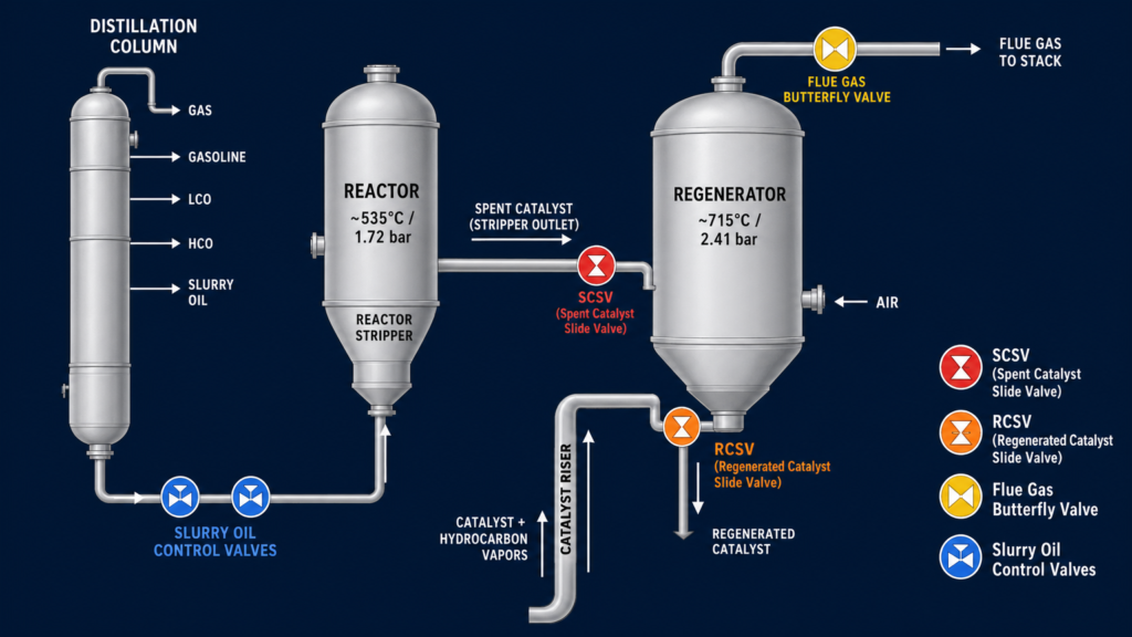
FCCUでバルブの腐食がなぜこれほど深刻なのかを理解するには、運転条件と触媒自体の性質を調べる必要がある。FCCプロセスは、反応器と再生器という2つの主容器間で粉末触媒を連続循環させることに依存している。.
反応器では、長鎖炭化水素が気化し、約535℃の温度と約1.72バールの圧力で高温の触媒と接触して分解する。クラッキングプロセスでは、触媒上に炭素質コークスが堆積し、触媒を不活性化する。この “使用済み ”触媒は次に再生器に移され、そこで酸素が豊富な環境下、温度715℃、圧力約2.41 barでコークスが燃焼除去される。.
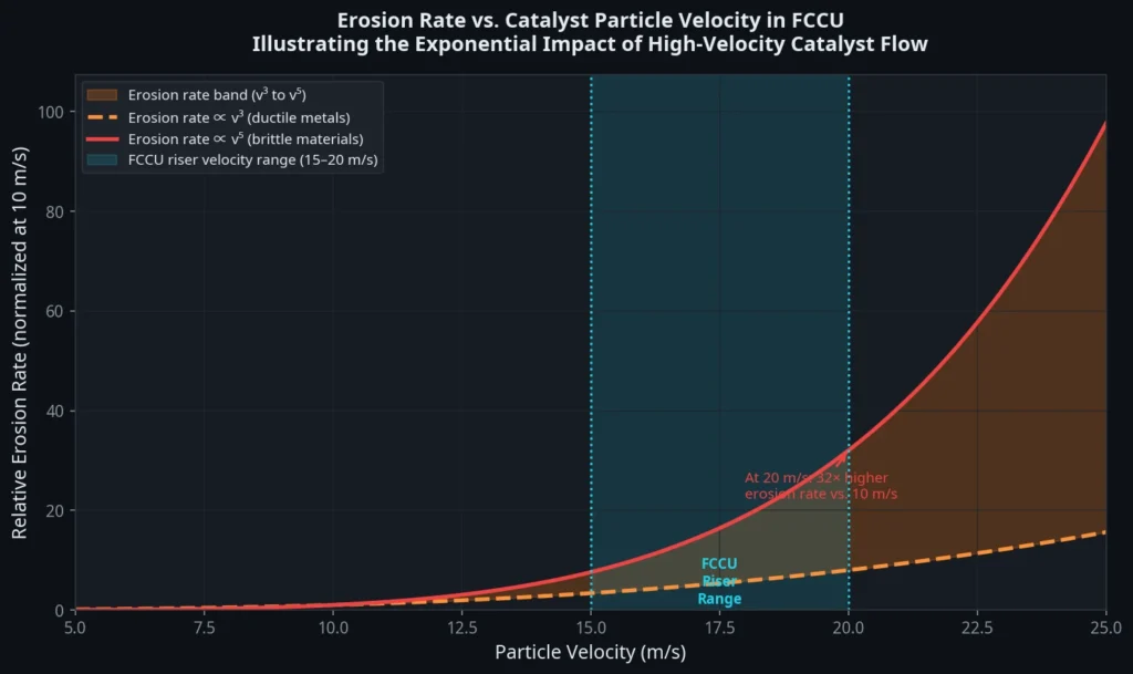
触媒自体は非常に研磨性が高い。通常、シリカ-アルミナ・マトリックス内のゼオライト(Y型フォージャサイト)で構成され、粒子の大きさは平均60~100マイクロメートル。アルミナとシリカの成分はモース硬度6~7で、石英に匹敵する。数百万個の硬質粒子が毎秒15~20メートルの速度でシステム内に送り込まれると、露出したバルブ表面に対して連続的な高温サンドブラスト媒体として作用します。.
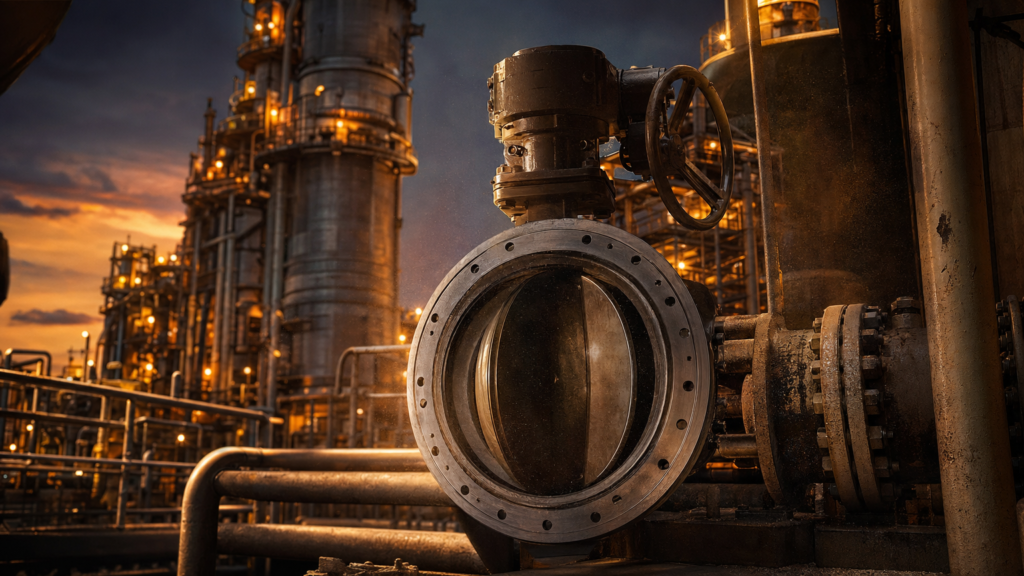
この過酷なサービスにさらされる主要なバルブ・ポジションには、使用済み触媒スライド・バルブ(SCSV)、再生触媒スライド・バルブ(RCSV)、排ガスバタフライ・バルブ、スラリー・オイル・コントロール・バルブなどがある。これらのバルブはいずれも、容赦ない侵食攻撃にもかかわらず、正確な制御と緊密なシャットオフを維持しなければならない。.
FCCUサービスにおけるバルブ浸食のメカニズム
FCCUにおけるバルブの侵食は、主に固体粒子の衝突と摩耗によって引き起こされる。硬い触媒粒子がバルブの金属表面に高速で衝突すると、微細な量の材料が除去される。時間の経過とともに、この累積的な材料損失はバルブの構造的完全性とシール能力を損ないます。.
侵食速度は線形ではなく、粒子の速度に指数関数的に関係する。延性金属の場合、浸食速度は一般的に流速の3乗に比例しますが($v^3$)、脆性材料の場合は流速の5乗に比例します($v^5$)。このことは、流速がわずかに増加するだけでも(部分的に開いたバルブディスクを横切る局所的な圧力降下が原因かもしれない)、侵食速度が劇的に加速される可能性があることを意味する。.
さらに、侵食プロセスは高温環境によって悪化することが多い。500℃を超える温度では、多くの標準的なバルブ材料の硬度と降伏強度が著しく低下する。この高温軟化により、金属は触媒粒子による切削や塑性加工を受けやすくなる。さらに、硫黄化合物やナフテン酸が存在すると、金属上の保護酸化膜が触媒によって継続的に剥離され、新鮮な金属が急速な化学攻撃にさらされる浸食腐食が発生する可能性があります。.
もう一つの重要な要因は、触媒の “微粉 ”の蓄積である。触媒が循環するにつれて、粒子は互いに、また装置の壁に衝突し、ファインと呼ばれる20マイクロメートル以下の小さな断片に分解される。これらの微粉は、メインフラクショネーターの下部にあるスラリーオイル回路に蓄積する傾向がある。ターンアラウンドのサイクルが進むにつれて、このような研磨性の高い微粉の濃度が高くなり、運転の最後の数年間は侵食率が急上昇します。.
バルブ浸食がもたらすもの
FCCUでバルブの浸食を軽減できなかった場合の影響は、損傷したコンポーネントの交換費用にとどまりません。腐食の未然防止は、運転効率、プラントの安全性、そして収益に影響を与えます。.
操業と経済への影響
バルブの着座面やディスクエッジが侵食されると、バルブはタイトなシャットオフ能力を失う。この内部リークにより、触媒や炭化水素が意図された制御ポイントをバイパスする。スライドバルブの場合、オリフィスプレートやガイドの浸食が激しいと差圧制御ができなくなり、反応器や再生器内の触媒レベルを適正に保つことが困難になる。.
故障したバルブを補うために、オペレーターは、安全な運転パラメータを維持するために処理能力を低下させ、ユニットをディレーティングすることを余儀なくされることが多い。予定されたターンアラウンドの前にバルブが完全に故障した場合、製油所は計画外のシャットダウンに直面する。予定外のFCCU停止による経済的影響は驚異的であり、緊急メンテナンスと交換部品の直接費用は含まれないものの、1日あたり$1百万から$2百万の生産損失が発生することが多い。.
安全性への影響
バルブ浸食の最も深刻な結果は、大惨事の安全事故の可能性である。FCCUは、反応器の炭化水素リッチな環境と再生器の酸素リッチな環境を分離するために、微妙な圧力バランスと物理的な触媒バリアに依存している。.
使用済み触媒スライド・バルブ(SCSV)が深刻な侵食を受け、触媒シールを維持できなくなると、炭化水素が再生器に逆流する可能性がある。これらの炭化水素が再生器内の空気と混合すると、しばしば大爆発を起こす。.
“米国化学物質安全・危険調査委員会(CSB)は、FCCUスライドバルブの浸食が重要な役割を果たした複数の製油所事故を調査した。2018年のハスキー・スペリオール製油所の爆発事故では、CSBは、製油所が5年間のターンアラウンドサイクルでSCSVの深刻な浸食速度を ‘正常化 ’し、触媒バリアの喪失とそれに続く爆発につながり、36人の作業員が負傷したことを発見した。”
これらの事故は、FCCU環境の侵食力に耐えるよう特別に設計されたバルブを選択することの重要性を強調している。.
従来のバルブ設計の限界
標準的なバルブの設計と材質は、FCCU触媒の使用には全く不適当である。炭素鋼や標準的なオーステナイト系ステンレス鋼(316L など)の硬度は HRC 20~25 の範囲であり、研磨性の高いシリカ・アルミナ触媒に対する耐性はほとんどない。PTFEやエラストマーを使用したソフトシーテッドバルブは、その熱的限界をはるかに超える極端な温度によって即座に破壊される。.
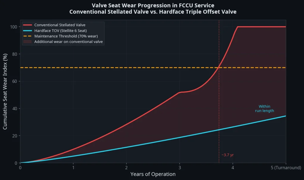
歴史的に、耐摩耗性を向上させる業界標準は、従来のバルブの着座面にステライト溶接オーバーレイを施すことでした。コバルト-クロム-タングステン合金であるステライト 6 は、HRC 38~44 の硬度を持ち、500℃まで機械的特性を維持します。ステレーテッド・バルブ」は、ターンアラウンド・サイクルの初期には十分な性能を発揮するが、運転が進むにつれて物足りなくなることが多い。.
従来のバタフライバルブの主な限界は、ステライト・オーバーレイを使用したものであっても、シーリングを摩擦に頼っていることである。同心またはダブルオフセットデザインの場合、ディスクは閉鎖の最終段階でシートと摩擦します。研磨触媒の粉塵が多い環境では、この摩擦作用によって粒子が座面に研磨され、摩耗が加速されます。ステライト層が摩耗すると、より柔らかい母材が露出し、急速な破損につながります。.
ハードフェイスシートデザインとトリプルオフセットジオメトリーのケース
最新の製油所で要求される運転時間の延長を達成するために、FCCUで使用されるバルブには、高度な硬質フェーシング材と摩擦のない機械設計の組み合わせが必要です。.
高度なハードフェーシング材料
ハードフェーシングは、より軟らかく強靭な母材に耐摩耗性材料の層を塗布することを含む。これにより、圧力封じ込めに必要な構造的延性を維持しながら、浸食に耐えるために必要な表面硬度が得られる。.
ステライト 6 は、耐侵食性、耐食性、耐かじり性のバランスが優れているため、溶接肉盛用として依然として一般的な選択肢ですが、特定の過酷な用途では、他の材料も人気を集めています。炭化タングステン-コバルト(WC-Co)および炭化クロム-ニッケルクロム(Cr₃C₂-NiCr)などの高速酸素燃料(HVOF)溶射皮膜は、HRC 65を超える極端な硬度レベルを提供します。これらのコーティングは、機械的に結合した緻密な層を形成し、摺動摩耗や粒子衝撃に対して優れた保護を提供します。.
下の表は、FCCU バルブで使用される最も一般的なハードフェース・シート材料の主な特性をまとめたもので、エンジニアは各バルブ位置の特定の要求に材料を適合させることができます。.
| 素材 | 硬度(HRC) | 最高使用温度最高使用温度. | 申込方法 | 最適 |
|---|---|---|---|---|
| 316Lステンレス(コーティングなし) | 25 | 870°C | — | 一般サービス(触媒には推奨されない) |
| ステライト6(Co-Cr-W) | 38-44 | 500°C | 溶接肉盛、レーザークラッディング | リアクター/リジェネレーター用スライドバルブ、バタフライバルブディスク |
| ステライト1(Co-Cr-W、高C) | 50-55 | 500°C | 溶接オーバーレイ | 高摩耗バタフライバルブ用ハードフェーシング |
| コルモノイ6(Ni-Cr-B-Si) | 55-60 | 870°C | 溶接オーバーレイ | 高温、高摩耗バタフライバルブ |
| HVOF Cr₃C₂-NiCr | 60-65 | 850°C | HVOF溶射 | 高温浸食性サービス |
| HVOF WC-Co | 65-70+ | 450°C | HVOF溶射 | 低温、極度の磨耗(スラリーサービス) |
| セラミック(Al₂O₃) | ~75(モース9) | >1000°C | 焼結インサート | 最も過酷なスラリーオイルサービス |
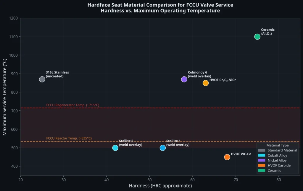
触媒微粉の濃度が最も高い、最も過酷なスラリー油の用途では、酸化アルミニウム($Al_2O_3$)やジルコニア($ZrO_2$)のような高度なセラミック材料が採用されることがある。これらのセラミックはモース硬度9で、金属製ハードフェーシングよりも脆いが、非常に優れた耐熱衝撃性を持つ。.
トリプル・オフセットの優位性
ハードフェーシングの真のポテンシャルは、摩擦のない形状である トリプルオフセットバタフライバルブ(TOV).
トリプル・オフセット・デザインは、3つの異なる幾何学的なオフセットを取り入れている:
- シャフト中心線オフセット: シャフトはシール面の後方に配置され、シートリングを途切れることなく連続させることができる。.
- ラテラル・シャフト・オフセット: シャフトはパイプの中心線から横方向にオフセットされており、カムのような動きを生み出し、開口と同時にディスクをシートから持ち上げる。.
- 円錐形の座軸: 座面は直円筒ではなく、傾斜円錐として加工される。.
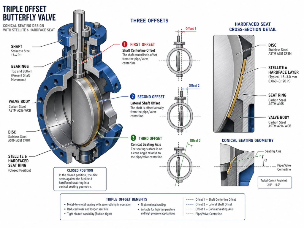
このユニークな形状により、バルブディスクは完全に閉じる瞬間にのみ弁座に接触します。バルブの移動中、擦れや摩擦は全くありません。ステライト6硬質フェースをTOVのディスクエッジとシートリングの両方に適用すると、摩擦による摩耗がほとんどない金属間シールが得られます。.
硬質表面は互いに擦れ合うことがないため、ステライト層の完全性は保たれます。バルブはトルクの圧縮力のみに頼って気泡密閉を達成し、シール面の間に閉じ込められた触媒粒子の研磨性を効果的に中和します。材料科学と機械工学のこの相乗効果により、ハードフェイス・トリプルオフセットバルブは、5年間のFCCUターンアラウンド・サイクル全体を通してゼロ・リーク性能を維持することができる。.
FCCU侵食サービス用バルブの指定
FCCUアプリケーションにバルブを指定する場合、エンジニアは基本的な圧力と温度の定格を超えたところに目を向けなければなりません。長期的な信頼性を確保するためには、バルブの選定に包括的なアプローチが必要です。.
以下の表は、FCCU のサービスポジション別に、バルブのタイプとハードフェーシングを選択する際の実用的なガイドとなる:
| サービス・ポジション | 流体 | 温度温度範囲 | 推奨バルブタイプ | 推奨ハードフェーシング |
|---|---|---|---|---|
| 使用済み触媒スライドバルブ(SCSV) | 密相触媒 | 500-600°C | 耐火物ライニング付きスライドバルブ | ディスクとオリフィス上のステライト6溶接オーバーレイ |
| 再生触媒スライドバルブ(RCSV) | 密相触媒 | 650-720°C | 耐火物ライニング付きスライドバルブ | ディスクとオリフィス上のステライト6溶接オーバーレイ |
| 排ガス用バタフライバルブ | 排ガス+巻き込み触媒 | 600-720°C | トリプルオフセットバタフライバルブ | ディスクエッジとシートリングにステライト6 |
| エキスパンダー・インレット/バイパス | 高速排ガス | 600-720°C | トリプルオフセットバタフライバルブ | ステライト6またはコルモノイ6オーバーレイ |
| スラリーオイルコントロールバルブ | 重油中の触媒微粉 | 300-400°C | シビアサービス制御弁 | HVOF WC-Coまたはセラミックインサート |
| スラリー油分離 | 重油中の触媒微粉 | 300-400°C | メタル・トゥ・メタル・シーテッドTOV | HVOF Cr₃C₂-NiCrまたはWC-Co |
バルブの種類の選択以外にも、エンジニアは以下の原則を守るべきである:
ノン・ラビング・デザインを要求する。. クリティカル・アイソレーションについては、次のように指定する。 トリプルオフセットバタフライバルブ 摩擦摩耗をなくすためにノン・ラビング・クロージャー・メカニズムは、触媒サービスにおけるあらゆるハードフェース・コーティングの完全性を維持する上で、最も重要な設計上の特徴である。.
適切なハードフェーシングを指定する。. ハードフェーシング材が、使用されるサービスの 温度および摩耗プロファイルに適合していることを確 認すること。ステライト6溶接オーバーレイは、一般的に高温 の原子炉/再生炉用途に適しているが、HVOF 超硬合金は、低温、高摩耗のスラリーサービスに 適している場合がある。などの専門メーカーにご相談ください。 カーターバルブ を参照して、特定の条件に最適な材料の選択を確認してください。.
業界標準を遵守する。. バルブが、バタフライバルブ設計の API 609、リークテストの API 598、サワーサービス条件(H₂S)が存在する場合の NACE MR0175 / ISO 15156 を含む関連規格に準拠していることを確認する。重要な隔離サービスについては、API 609カテゴリーB(トリプルオフセット)バルブの仕様を検討すること。.
ボディ・プロテクションを考える。. 侵食性の高い流路では、バルブ本体の保護が必要になる場合があります。内部耐火物ライニングを施したコールドウォールバルブや、六角メッシュと耐侵食性キャスタブルを施したホットウォールバルブを適切に設計すること。これは、直接触媒を使用するスライ ドバルブや大口径バタフライバルブにとって特に重要である。.
バルブのエロージョンのメカニズムを理解し、高度なハードフェイスシート設計に投資することで、製油所は計画外停止のリスクを大幅に削減し、プロセスの安全性を高め、流動接触分解装置の収益性を最大化することができます。具体的なFCCUバルブの要件については、当社のエンジニアリングチームにご相談ください、, 連絡先 カーターバルブ 技術相談のために。.
よくある質問(FAQ)
FCCUのバルブびらんの原因は何ですか?
FCCUにおけるバルブの腐食は、主に分解プロセスで使用されるシリカ-アルミナ触媒粒子の高速衝撃と摩耗によって引き起こされる。これらの粒子は非常に硬く、バルブの内部部品に対してサンドブラスト媒体のような働きをします。.
なぜ標準的なステンレス鋼バルブはFCCUサービスで故障するのか?
316Lなどの標準的なオーステナイト系ステンレ ス鋼は、硬度が比較的低く(HRC 25前後)、FCCUの高い運転温度 (500℃~715℃)で強度が著しく低下する。これらのステンレス鋼は、研磨性の触媒粒子 によってすぐに切断され、摩耗する。.
ステライト・ハードフェーシングとは何ですか?
ステライトは、コバルト-クロム-タングステン合金の一種で、卓越した耐摩耗性、硬度、高温での機械的特性保持能力で知られています。ステライト6は、触媒の浸食から保護するため、バルブ着座面の溶接オーバーレイとして一般的に使用されています。.
トリプルオフセット・バタフライバルブは、どのようにしてシート摩耗を防ぐのですか?
トリプルオフセットバタフライバルブは、カムのような閉鎖を作り出す3つの異なるオフセットを持つユニークな形状を利用しています。この設計により、バルブディスクがシートと接触するのは最終的な閉まり具合のみとなり、従来のバルブで急速に摩耗する原因となる擦れや摩擦がなくなります。.
FCCUでスライドバルブが故障した場合、どのような影響がありますか?
スライドバルブ、特に使用済み触媒スライドバルブの故障は、反応器と再生器の間の触媒バリアの喪失につながる可能性がある。これにより、再生器内で炭化水素が空気と混合し、いくつかの有名な製油所事故で見られたように、爆発の深刻なリスクが生じる。.
FCCU用のダブルオフセットバタフライバルブとトリプルオフセットバタフライバルブの違いは何ですか?
ダブルオフセットバタフライバルブでは、閉鎖時にディスクとシートが僅かに接触するため、摩擦摩耗が発生します。A トリプルオフセットバタフライバルブ は、第3の幾何学的オフセット(円錐状の着座軸)を使用し、完全に摩擦のない、カムのような閉鎖部を作り出します。これにより、摩擦による摩耗が完全に排除され、研磨性の高いFCCUサービスにおいてはるかに優れています。.
FCCUアプリケーションに適したバルブはどのように選べばよいですか?
適切なバルブを選択するには、流体の種類、温度、圧力、粒子濃度、必要なサイクル寿命を含むサービス条件の詳細な分析が必要です。カーターバルブのエンジニアリングチームは製油所用途の過酷なサービスバルブの選定を専門としています。私たちは次のことをお勧めします。 チームへの連絡 をプロセスデータシートと一緒にお送りください。.
参考文献
[1] ウィキペディアの投稿者“流動接触分解.”ウィキペディア フリー百科事典.
[2] Oloruntoba, A., et al.“流動接触分解(FCC)の最新レビュー.”エネルギー、2022年.
[3] BLAC Inc.“FCCUバルブ” https://www.blacinc.com/fccu-valves
[4] マン、B.S. “HVOF/TiAlN PVDコーティングの腐食・侵食性能.”ウェア、2006年。.
[5] ハシム、M. “流動接触分解腐食:包括的レビュー.”LinkedIn Pulse、2023年。.
[6] バルメット“FCCUにおける触媒微粉による侵食と磨耗を除去する方法.”フローコントロールインサイト、2013年。.
[7] グレース“流動化原理によるFCCリアクターのレベル制御のトラブルシューティング.”2024.
[8] 米国化学物質安全・危険調査委員会(CSB)。“ハスキー・スペリオール製油所爆発火災調査報告書.”2022.
[9] バルブマガジン“バルブのハードフェーシング:材料とプロセス.”2019.
[10] ステライト“ステライト 6 合金 - 技術データ.”
[11] ソンガー、K.“シビアサービスバルブ用HVOFコーティング.”バルブマガジン、2025年.
[12] API 規格 609。「バタフライバルブ:ダブルフランジ、ラグタイプ、ウェーハタイプ“.米国石油協会。.
[13] NACE MR0175 / ISO 15156.“石油及び天然ガス産業-石油及びガス生産における H2S を含む環境で使用するための材料”.NACE International.