


Specifying a control valve without defining its allowable leakage rate is a recipe for operational disaster. When a valve is commanded to close, plant operators assume the flow of fluid stops completely. However, in the mechanical reality of industrial valves, “closed” rarely means a perfect, absolute seal.
If a valve leaks slightly when closed, it might be acceptable in a cooling water bypass loop. But if that same valve leaks toxic chemicals or high-pressure steam, the consequences range from ruined product batches to catastrophic safety incidents. Engineers need a standardized, quantifiable method to define exactly how much leakage is acceptable for a specific application.
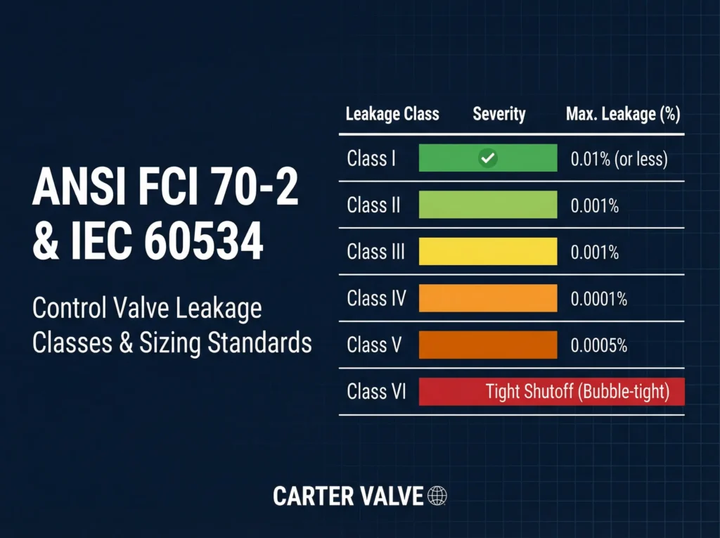
The ANSI/FCI 70-2 standard provides this exact framework, defining six distinct classes of seat leakage. When combined with the IEC 60534 standard for aerodynamic and hydrodynamic sizing, these two documents form the foundation of proper control valve specification. Understanding these standards is critical for selecting the right valve trim, ensuring process safety, and avoiding costly over-specification.
What Are ANSI/FCI 70-2 Seat Leakage Classes?
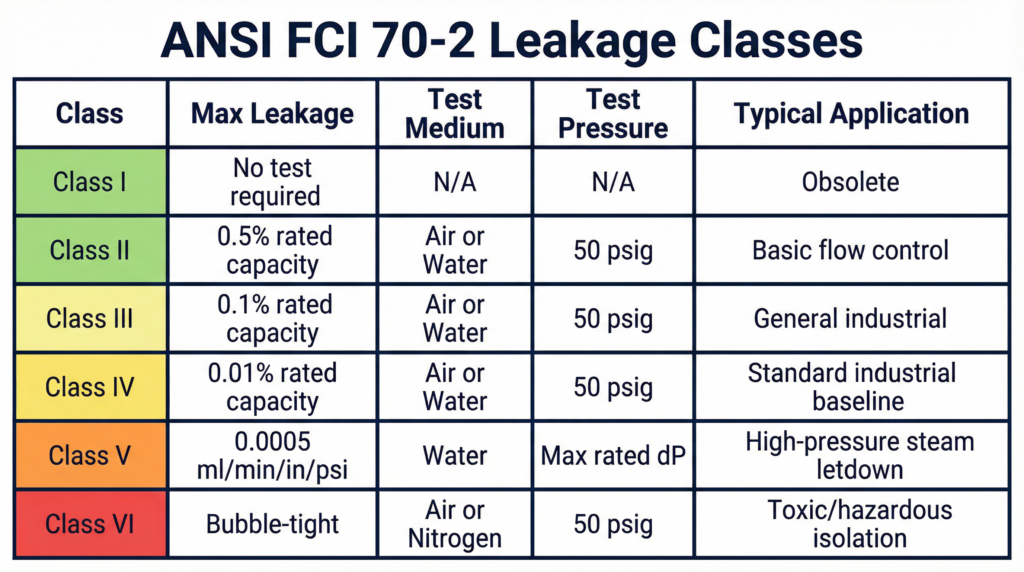
The American National Standards Institute (ANSI) and the Fluid Controls Institute (FCI) developed the 70-2 standard to establish uniform testing procedures and maximum allowable leakage rates for control valves. The standard defines six classes, ranging from Class I (the least stringent) to Class VI (the most stringent).
It is crucial to understand that these classes define the leakage rate of a new valve under controlled factory test conditions. They do not guarantee that the valve will maintain that exact leakage rate after years of service in a corrosive or erosive environment.
Understanding Each Leakage Class (I–VI)
The six classes are designed to match the mechanical capabilities of different valve designs and the operational requirements of various industries.
Class I: This class is largely obsolete. It is an agreement between the user and the manufacturer that no specific test is required. It is rarely specified in modern industrial applications.
Class II: This class allows a maximum leakage of 0.5% of the valve’s rated capacity. It is typically achieved with standard commercial double-port globe valves or balanced single-port valves with metal-to-metal seats. It is suitable for basic flow control where tight shut-off is not critical.
Class III: This class allows a maximum leakage of 0.1% of the rated capacity. It requires improved seat lapping and tighter manufacturing tolerances than Class II. It is often specified for Allzweck-Durchgangsregelventil applications where moderate shut-off is needed.
Class IV: This is the standard industrial baseline for single-port metal-seated valves. It allows a maximum leakage of 0.01% of the rated capacity. Achieving Class IV requires precision machining and high-quality actuator seating force. It is the default specification for most Produktpalette der Regelventile applications.
Class V: This class represents a significant jump in stringency. The leakage is not based on a percentage of capacity, but rather a specific formula: 0.0005 ml of water per minute, per inch of port diameter, per psi of differential pressure. Class V is required for critical applications, such as high-pressure steam letdown, where even minor leakage would cause severe wire drawing and rapid seat destruction.
Class VI: Often referred to as “bubble-tight shut-off,” this is the most stringent class. The leakage is measured in bubbles of air or nitrogen per minute, depending on the port diameter. Achieving Class VI almost always requires a resilient elastomer or PTFE soft seat. It is specified when absolute isolation is required for safety or environmental reasons.
How Are Leakage Classes Tested?
The ANSI/FCI 70-2 standard dictates specific test procedures for each class to ensure consistency across manufacturers.
For Classes II, III, and IV, the test medium can be air or water at 50-125°F (10-52°C). The test pressure is typically 50 psig or the maximum operating differential pressure, whichever is lower. The leakage is measured and compared to the calculated percentage of the valve’s rated capacity (Cv).
Class V testing is significantly more rigorous. The test medium must be water. The test pressure must be the maximum specified operating differential pressure across the valve plug. Because the leakage allowance is so small, the test duration is longer, and the measurement must be highly precise.
Class VI testing requires air or nitrogen as the test medium. The test pressure is 50 psig or the maximum rated differential pressure, whichever is lower. The leakage is measured by capturing the escaping gas and counting the bubbles per minute using a standardized tube submerged in water.
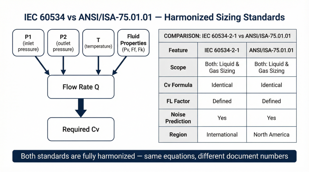
The IEC 60534 Sizing Standard
While ANSI/FCI 70-2 governs leakage, the International Electrotechnical Commission (IEC) 60534 standard governs the aerodynamic and hydrodynamic sizing of control valves. IEC 60534-2-1 and ANSI/ISA-75.01.01 are harmonized, meaning they use the same fundamental equations for calculating the required flow coefficient (Cv).
Sizing a valve correctly is just as critical as specifying the correct leakage class. If a valve is oversized, it will operate too close to the seat, leading to poor control resolution and rapid wire drawing, which quickly destroys the valve’s ability to meet its specified leakage class. If a valve is undersized, it will not be able to pass the required flow rate, creating a bottleneck in the process.
The IEC 60534 equations account for complex fluid dynamics, including the specific gravity of the fluid, the pressure drop across the valve, the vapor pressure of liquids, and the compressibility of gases. By accurately calculating the required Cv, engineers ensure the valve operates in its optimal mid-range, maximizing control precision and extending the lifespan of the seating surfaces.
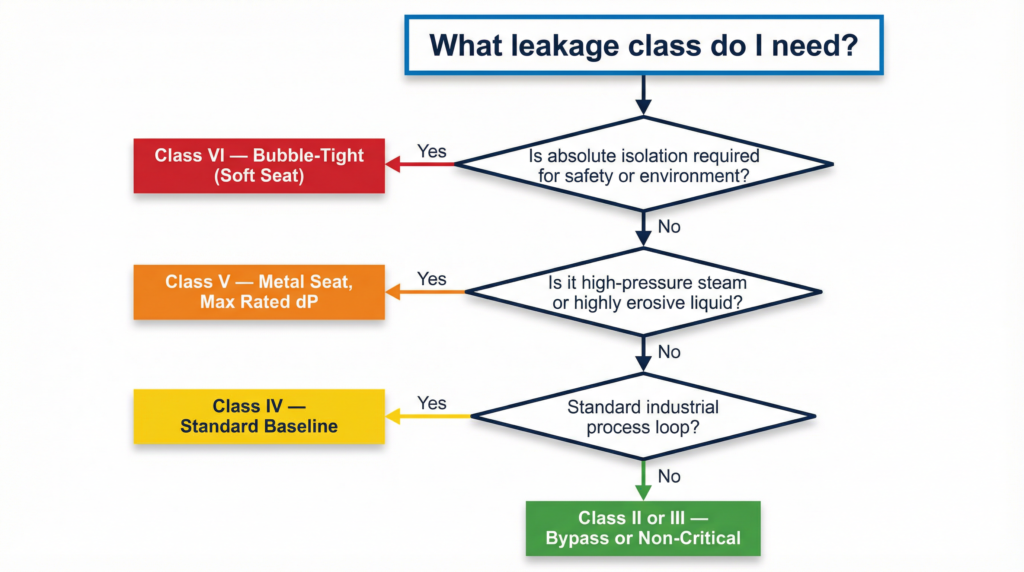
Practical Decision Tree for Class Selection
Selecting the correct leakage class requires a practical decision tree that balances operational needs, safety requirements, and cost. Over-specifying a Class VI soft-seated valve for a high-temperature steam application will result in immediate seat failure. Under-specifying a Class II valve for a toxic chemical line will result in a hazardous leak.
Step 1: Is absolute isolation required for safety or environmental compliance?
If yes, specify Class VI. Ensure the process temperature is compatible with soft elastomeric seats (typically below 400°F/204°C).
Step 2: Is the fluid high-pressure steam or a highly erosive liquid?
If yes, specify Class V. The metal-to-metal seating can withstand the temperature and velocity, and the stringent leakage requirement prevents wire drawing. This is critical for ANSI-Regelventil für hohe Beanspruchung applications.
Step 3: Is it a standard industrial process loop (water, low-pressure gas, oil)?
If yes, specify Class IV. This provides excellent shut-off for general control purposes without the added cost and manufacturing complexity of Class V or VI.
Step 4: Is it a bypass loop or a continuous flow application where tight shut-off is irrelevant?
If yes, Class II or III is acceptable, often utilizing balanced plug designs that require smaller, less expensive actuators.
Was CARTER auszeichnet
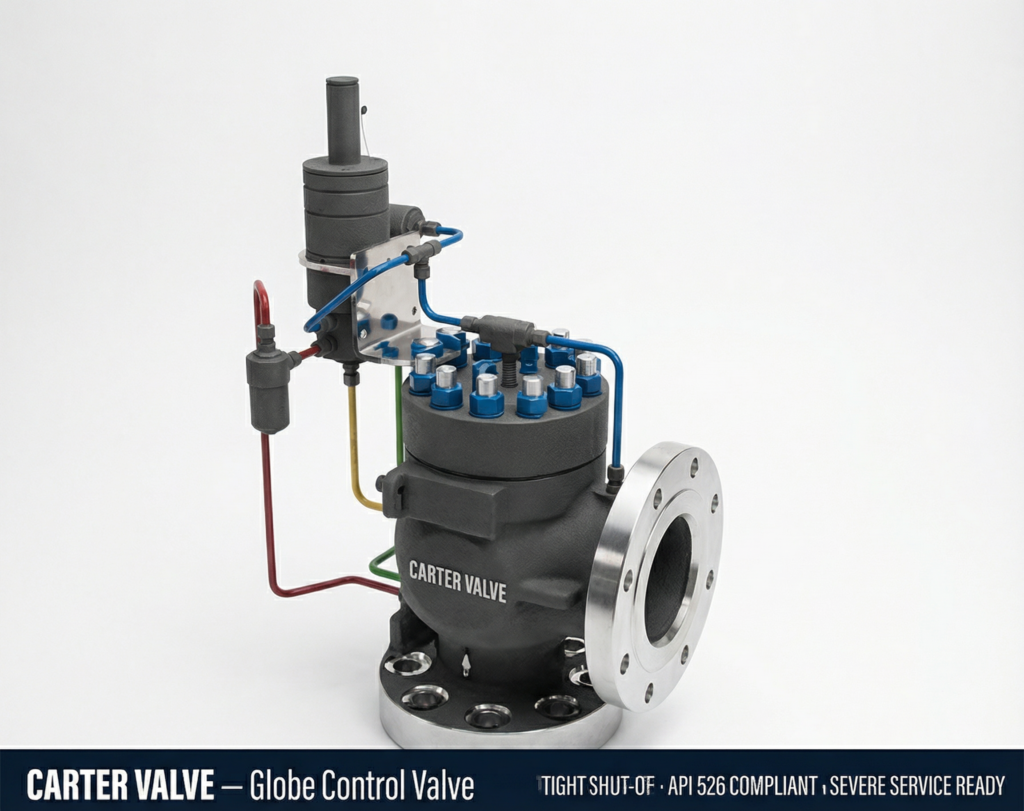
Carter Technologies manufactures a comprehensive portfolio of control valves engineered to meet and exceed the most stringent ANSI/FCI 70-2 and IEC 60534 standards. Our designs prioritize long-term stability, utilizing heavy-duty stem guiding and precision-lapped trim materials to ensure your valves maintain their specified leakage class long after installation.
We guarantee tight shut-off compliance across our entire range. Every valve we build is fully API 526 compliant and features a 98% set pressure tight shut-off guarantee. Whether you require a Class VI soft-seated valve for absolute isolation or a Class V solid Stellite trim for high-pressure steam letdown, our severe service capabilities ensure your process remains safe and efficient.
If you are struggling with internal leakage or complex sizing calculations, our team is available to review your process data and recommend the appropriate configuration. To learn more about our foundational technologies, review our guide on Was ist ein Steuerventil?. Für sicherheitskritische Anwendungen lesen Sie bitte unsere ESD-Ventil-Auswahlhilfe.
For a detailed technical consultation and custom sizing analysis, Kontakt zu unserem Ingenieurteam heute.