


Correct actuator sizing is one of the most common risk points in butterfly valve applications. Undersizing can lead to valves that fail to open after shutdown, stall part-way through stroke, or lose shutoff capability under pressure. Oversizing increases cost, stresses shafts and gearboxes, and can create control and seating problems.
For severe or critical isolation duties—such as molecular sieve service, high-temperature FCCU lines, or cryogenic LNG isolation—the consequences of a wrong torque assumption are not just operational but mechanical and safety-related.
This article explains how actuator sizing for butterfly valves should be approached in practice, with particular attention to breakaway torque, running and seating torque, safety factors, and the most common specification mistakes seen in projects.

1. What “actuator sizing” really means
Actuator sizing is not the same as selecting an actuator with a torque number “bigger than the valve.” A correct sizing exercise must confirm that the actuator can:
- Overcome breakaway torque at the worst credible conditions
- Provide sufficient running torque through the full 0–90° stroke
- Deliver adequate seating/unseating torque at the required differential pressure
- Do this with an appropriate margin for uncertainty, degradation, and service variability
For butterfly valves, torque demand is not constant across the stroke. It typically peaks at:
- The closed position (breakaway and final seating), and
- Sometimes near mid-stroke, depending on disc profile, seat type, and pressure distribution.
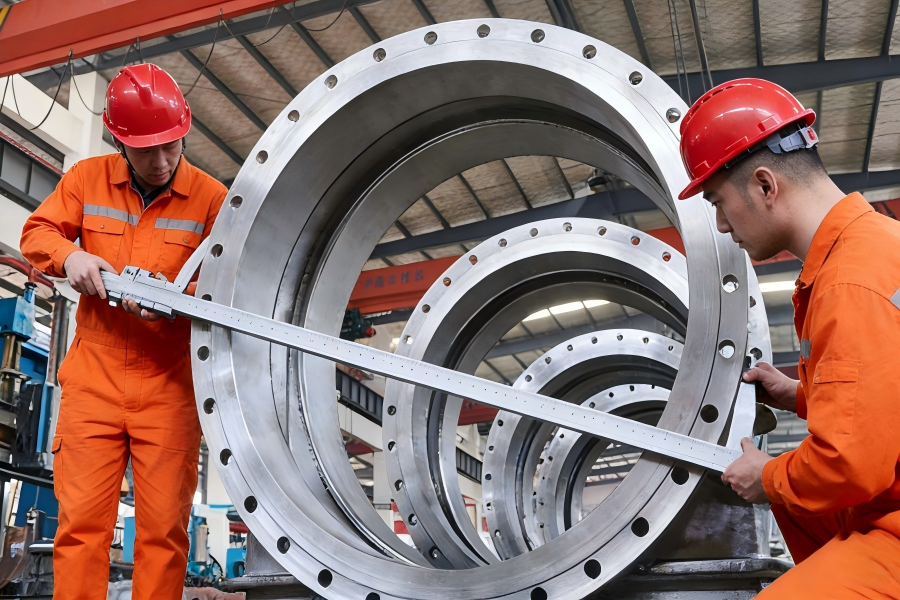
High-performance, triple offset, and multi-eccentric designs—such as six-eccentric butterfly valves—change how contact between disc and seat is developed. This improves sealing behaviour and wear characteristics, but it also means the torque curve shape is different from concentric or simple offset designs. Actuator sizing must therefore be based on the actual torque curve of the specific valve design, not on a generic assumption.
You can check the Actuator and Valve Standards Overview here.
2. Breakaway torque: why it matters most
Breakaway torque is the torque required to start moving the valve from the fully closed position. In many services, this is the maximum torque the actuator will ever see.
Several factors drive breakaway torque:
- Seat contact stress (especially for metal-to-metal or high-interference soft seats)
- Static friction after dwell time
- Process pressure acting on the disc
- Temperature effects (thermal expansion, material property changes)
- Deposits or sticking from the process medium
For severe isolation duties, breakaway torque after a long closed period can be significantly higher than the torque measured during shop testing. This is why relying only on “nominal” or “catalogue” torque values is risky unless the test conditions and assumptions are clearly stated.
For example:
- In high-temperature FCCU service, thermal distortion and coke fines can increase unseating torque.
- In molecular sieve service, fine particles can migrate into sealing areas during cycling.
- In cryogenic LNG isolation, temperature gradients and material contraction can change contact conditions between disc and seat.
A robust actuator selection therefore starts with the worst-case breakaway torque under defined conditions, not with average operating torque.
3. Other torque components: running and seating
While breakaway torque often governs actuator size, two other components must also be checked.
3.1 Running torque
Running torque is the torque required to keep the valve moving once it has broken free. It depends on:
- Bearing friction
- Seat contact profile during travel
- Hydrodynamic forces from the flowing medium
In some valve designs and pressure regimes, the maximum running torque can occur around mid-stroke, not at the ends. This is especially relevant for throttling or modulating duties, or where high differential pressure exists across a partially open disc.
3.2 Seating torque
Seating torque is the torque required to achieve the specified shutoff performance at the closed position. For metal-to-metal seated or zero-leakage isolation concepts (where shutoff is verified against a defined standard and test method), this torque must be sufficient to:
- Establish the intended contact stress
- Compensate for pressure-assisted or pressure-opposed sealing geometry
- Maintain tightness over the specified pressure and temperature range
If seating torque is underestimated, the valve may pass acceptance testing when new but lose tightness in service as surfaces wear or conditions change.
4. The role of safety factors (and how to use them properly)
A safety factor is not a substitute for poor data. It is a structured allowance for uncertainty and variability, such as:
- Manufacturing tolerances
- Changes in friction over time
- Process condition deviations from design
- Aging, wear, or contamination
In practice, safety factors are applied to the maximum required torque (often breakaway or peak running torque). The exact value should be justified by:
- How well the torque has been characterised and tested
- How severe or variable the service is
- How critical the valve function is to plant safety or availability
For clean, well-defined services with well-documented test data, a lower margin may be appropriate. For severe, dirty, high-temperature, or infrequently operated isolation valves, a higher margin is often justified.
What should be avoided is the “blind multiplier” approach—adding an arbitrary large factor without understanding whether the base torque is realistic. This can result in excessive actuator output that overloads shafts, keys, gearboxes, or seat structures.
5. Pneumatic, electric, and hydraulic actuators: sizing implications
The sizing logic is similar for all actuator types, but the delivery of torque over the stroke differs.
- Pneumatic actuators: Output torque varies with air supply pressure and spring configuration. Both air-to-open and air-to-close cases must be checked, including the end-of-stroke torque where breakaway or seating is required.
- Electric actuators: Typically provide relatively flat torque curves, but must be checked for stall torque limits, duty cycle, and thermal capacity, especially in high-cycling or high-ambient-temperature services.
- Hydraulic actuators: Offer high torque in compact packages, but sizing must consider minimum available hydraulic pressure and fail-safe requirements.
In all cases, the actuator must be matched to the worst-case required torque at the relevant point in the stroke, not just to a nominal valve size.
6. How valve design influences torque assumptions
Different butterfly valve designs produce very different torque characteristics:
- High-performance (double offset) butterfly valves reduce seat rubbing during opening and closing, lowering wear and stabilising torque over life.
- Triple offset butterfly valves use a conical sealing geometry that eliminates continuous seat contact during travel, changing both breakaway and seating torque profiles.
- Six-eccentric butterfly valves further refine the contact path, typically aiming for a more progressive engagement and more distributed contact stress, which affects both the peak torque and how it develops near the closed position.
- Metal-to-metal seated isolation valves rely on controlled contact stress rather than elastic deformation, making accurate seating torque definition especially important.
Because of these differences, actuator sizing should always be based on torque data for the specific valve design and size, ideally supported by test procedures or documented calculation methods.
7. Common mistakes in actuator sizing
7.1 Using “typical” torque instead of worst-case torque
Catalogues often show representative or test-bench values. If the test pressure, temperature, and medium are not the same as the project conditions, these values may not be conservative enough.
7.2 Ignoring breakaway after long dwell
Valves that remain closed for long periods can develop higher static friction, deposits, or seat adhesion. Sizing only on “dynamic” torque can result in a valve that opens fine during commissioning but fails after months of operation.
7.3 Applying excessive safety factors without checking the load path
Oversizing the actuator can transfer excessive loads into the valve shaft, disc, seat, or gearbox. The valve and actuator should be considered as a system, not as independent components.
7.4 Not checking both directions of operation
For fail-open or fail-close configurations, the spring side of a pneumatic actuator often has lower available torque than the air-driven side. Both must be verified against the required torque curve.
7.5 Overlooking temperature and material effects
Friction coefficients, clearances, and material stiffness change with temperature. High-temperature and cryogenic services deserve explicit review rather than room-temperature assumptions.
8. A practical sizing workflow
A disciplined approach typically includes:
- Define process conditions: pressure, temperature, medium, cycling frequency, and required shutoff performance.
- Obtain or calculate the valve torque curve for these conditions, including breakaway, running, and seating torque.
- Identify the maximum required torque at any point in the stroke.
- Apply a justified safety factor based on service severity and data quality.
- Select an actuator whose available torque curve exceeds the required torque curve with margin in all relevant positions and operating modes.
- Verify mechanical interfaces (shaft, key, coupling, gearbox) for the resulting loads.
- Document the assumptions and limits (e.g., minimum supply pressure, maximum temperature, test basis).
9. Why this matters for severe-service butterfly valves
In critical isolation services, such as molecular sieve switching, FCCU isolation, or cryogenic LNG duty, actuator sizing is directly linked to:
- The ability to achieve and maintain the required shutoff class
- The predictability of operation after long dwell periods
- The mechanical life of both valve and actuator
- The risk profile of start-up, shutdown, and emergency operation
Engineered solutions—such as multi-eccentric or metal-to-metal seated butterfly valves—are typically selected to control sealing behaviour and wear. To realise those benefits in the field, the actuator must be sized with the same level of engineering discipline.
10. Final remarks
Actuator sizing for butterfly valves is not a checkbox exercise. It is a small but critical piece of system engineering that links valve design, process conditions, and operational reliability.
For projects where shutoff integrity, repeatability, and long-term stability matter, torque assumptions should be transparent, test methods or calculation bases should be stated, and safety factors should be applied with intent—not habit.
If you are specifying or reviewing actuated butterfly valves for demanding isolation duties, it is worth treating torque data and actuator selection as part of the valve engineering scope, not as an afterthought.
Contact us for customized solution.