


When a control valve sounds like gravel is flowing through the pipeline, maintenance teams know they have a severe fluid dynamics problem. However, diagnosing the exact cause of the noise and vibration is often the most difficult part of the repair process. Two distinct phenomena, cavitation and flashing, share nearly identical starting conditions but require completely different engineering solutions.
Both conditions occur when the pressure of a liquid drops below its vapor pressure as it accelerates through the valve’s restriction. This pressure drop causes the liquid to boil instantly, creating a mixture of liquid and vapor bubbles. The critical difference lies in what happens to the fluid pressure after it passes through the valve and enters the downstream piping.
Misdiagnosing cavitation as flashing, or vice versa, leads to expensive sizing errors and premature valve failure. By understanding the distinct physical damage patterns, the role of the pressure recovery factor, and the specific application nuances, engineers can specify the correct trim materials and prevent catastrophic system downtime.
The Shared Origin: Pressure Drop at the Vena Contracta
To understand the difference between cavitation and flashing, you must first look at the fluid dynamics inside the valve body. As liquid approaches the valve plug and seat, the flow area narrows significantly. This narrowest point in the flow stream is known as the vena contracta. According to Bernoulli’s principle, as the fluid velocity increases at the vena contracta, the static pressure must decrease proportionally.
If the static pressure at the vena contracta drops below the vapor pressure of the liquid, the fluid physically cannot remain in a liquid state. It begins to boil instantly, creating thousands of microscopic vapor bubbles. This boiling occurs without any addition of heat, driven entirely by the severe pressure drop. Both cavitation and flashing begin exactly this way. The divergence occurs downstream of the vena contracta.
What Is Cavitation in Control Valves?
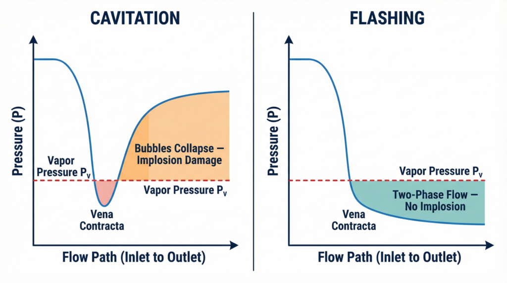
Control valve cavitation is a two-stage phenomenon. First, the vapor bubbles form at the vena contracta. Second, as the fluid exits the restriction and slows down, the pressure recovers above the vapor pressure. When the recovering pressure rises back above the vapor pressure, the vapor bubbles can no longer exist. They collapse inward on themselves in a fraction of a millisecond.
The collapse of these bubbles is extremely violent. The implosion generates a micro-jet of liquid that strikes the surrounding metal surfaces at supersonic speeds. The localized pressure generated by a single bubble collapse can exceed 3,000 psi. When millions of these bubbles implode continuously against the valve trim, they fatigue and tear away microscopic pieces of the metal.
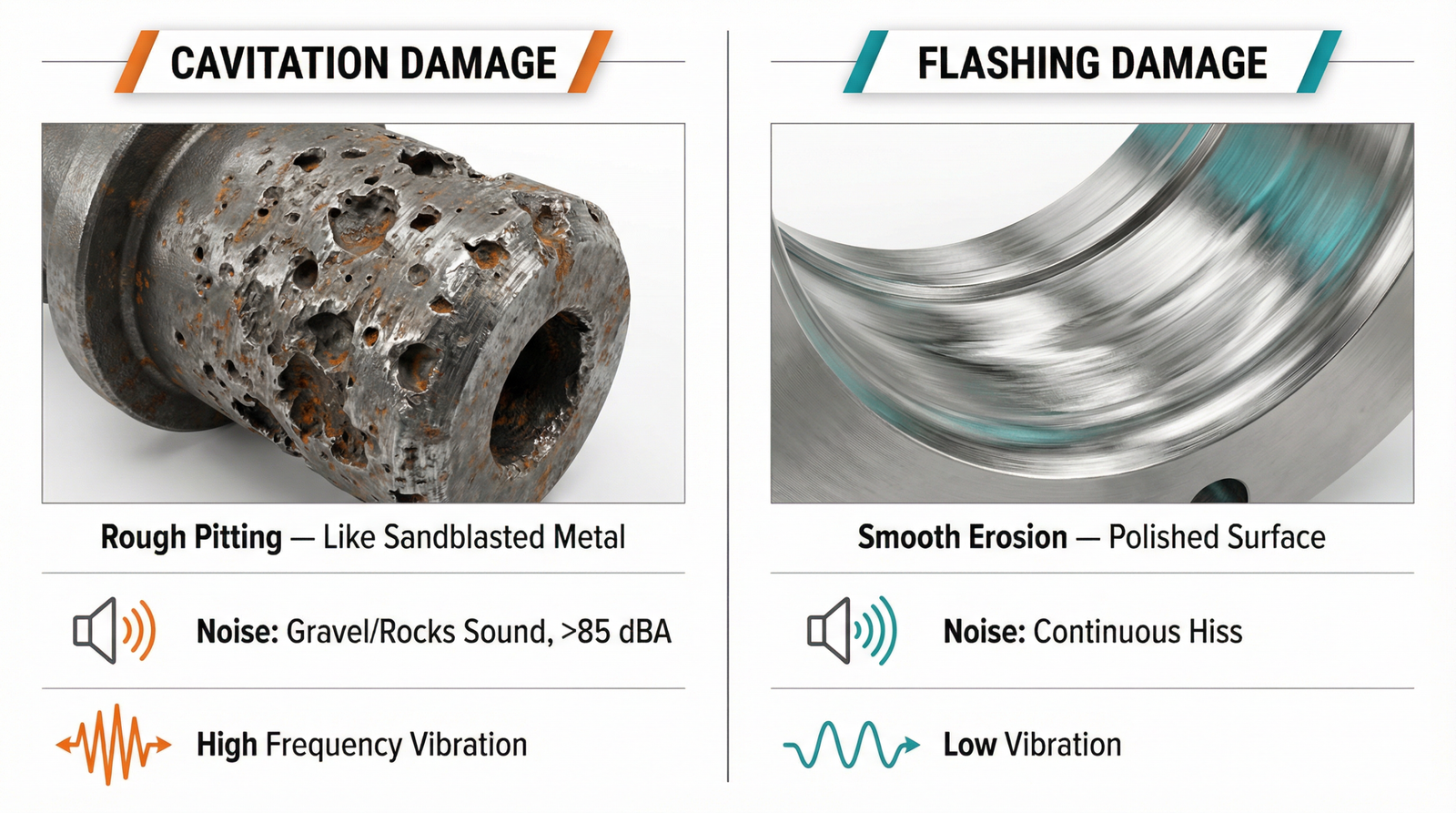
The damage caused by cavitation is highly distinctive. It appears as rough, cinder-like pitting on the metal surfaces, often looking as though the metal has been eaten away by a strong acid or blasted with coarse sand. This damage is typically concentrated near the seating surfaces and the immediate downstream piping. Severe cavitation also generates extreme noise levels, often exceeding 85 dBA, which sounds exactly like gravel flowing through the pipe.
What Is Flashing in Control Valves?
Flashing is a single-stage phenomenon. Like cavitation, vapor bubbles form at the vena contracta when the pressure drops below the vapor pressure. However, in a flashing application, the downstream pressure never recovers above the vapor pressure. The fluid remains a high-velocity mixture of liquid and vapor as it exits the valve.
Because the downstream pressure remains low, the vapor bubbles never collapse. Therefore, flashing does not cause the implosion shockwaves associated with cavitation. Instead, the high-velocity two-phase flow acts like a sandblaster, eroding the valve internals through sheer kinetic energy.
The physical damage caused by flashing is entirely different from cavitation. Flashing erosion leaves the metal surfaces smooth, shiny, and polished. The damage is usually spread over a much larger area, affecting the entire downstream side of the valve body and the adjacent piping. Flashing is particularly common in high-pressure oil and gas solutions where hot liquids are reduced to atmospheric pressure in separators.
Predicting the Phenomena: The Sigma Index and Pressure Recovery
Engineers rely on standardized calculations to predict whether a valve will experience cavitation or flashing. The Cavitation Index, commonly referred to as Sigma (σ), is the most reliable mathematical tool for this prediction. It is calculated as the ratio of the pressure drop available to the total pressure drop across the valve.
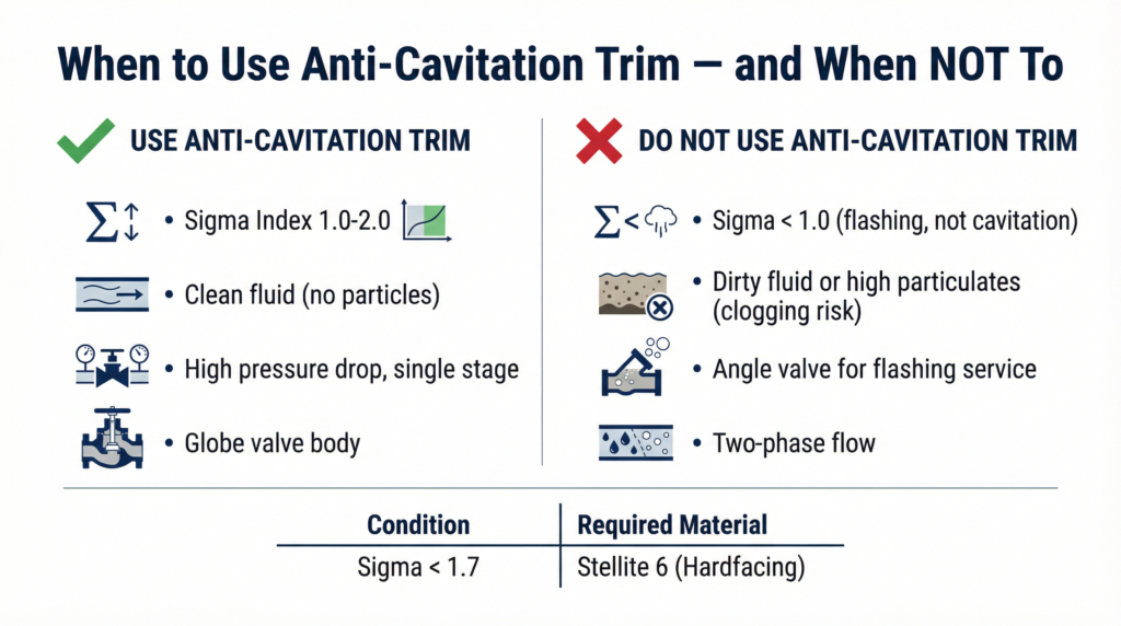
A Sigma value below 1.0 indicates that flashing will occur, as the downstream pressure will remain below the vapor pressure. A value between 1.0 and 1.5 indicates severe, damaging cavitation. Values between 1.5 and 2.0 suggest incipient cavitation with elevated noise levels, while a Sigma above 2.0 is generally considered safe for standard valve designs.
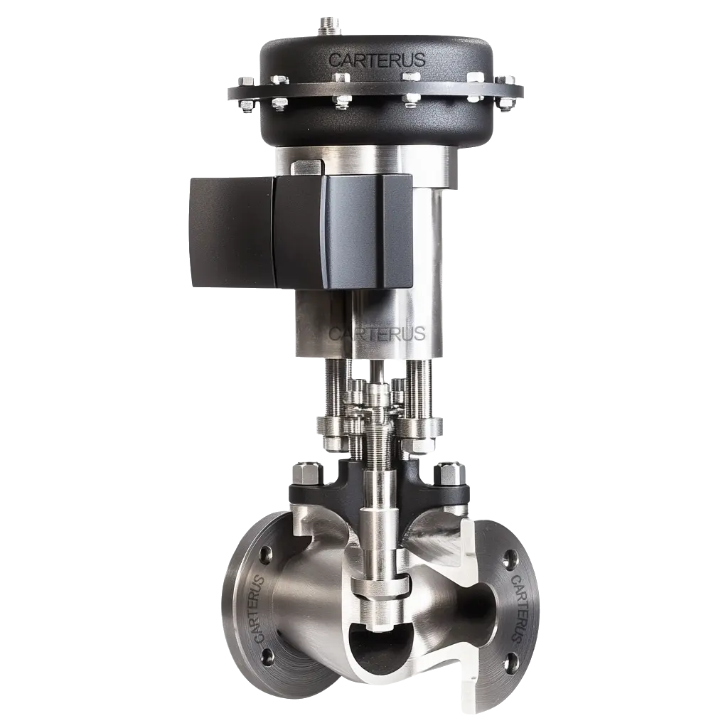
Another critical metric is the Liquid Pressure Recovery Factor, denoted as FL. This factor measures a valve’s internal geometry and its tendency to recover pressure after the vena contracta. Low FL valves are more prone to cavitation because they recover a significant amount of pressure, forcing the fluid back above the vapor pressure. For example, a general purpose globe control valve typically has a high FL of around 0.9, making it highly resistant to cavitation. Conversely, a standard butterfly valve has an FL closer to 0.6, meaning it recovers a significant amount of pressure and is highly susceptible to cavitation damage.
Field Diagnostic Checklist: Sound, Vibration, and Damage
Maintenance teams can often differentiate between cavitation and flashing without removing the valve from the pipeline. The key indicators are sound, vibration, and the location of the damage.
Sound: Severe cavitation sounds like gravel or rocks flowing through the pipe. The noise is loud, rattling, and highly irregular. Flashing sounds more like a continuous, high-pitched hiss or a rushing jet of air, similar to a high-velocity steam leak.
Vibration: Cavitation generates intense, high-frequency vibration that can loosen flange bolts and destroy a digital electro-pneumatic valve positioner. Flashing generates much less vibration, as there are no imploding shockwaves.
Damage Appearance: If the valve is removed for inspection, the damage pattern is the definitive diagnostic tool. Rough, cinder-like pitting indicates cavitation. Smooth, polished, and swept surfaces indicate flashing.
Engineering Solutions: When to Use Anti-Cavitation Trim
The solutions for cavitation and flashing are fundamentally different. You can prevent cavitation by modifying the pressure drop profile, but you cannot prevent flashing if the system requires a low downstream pressure.
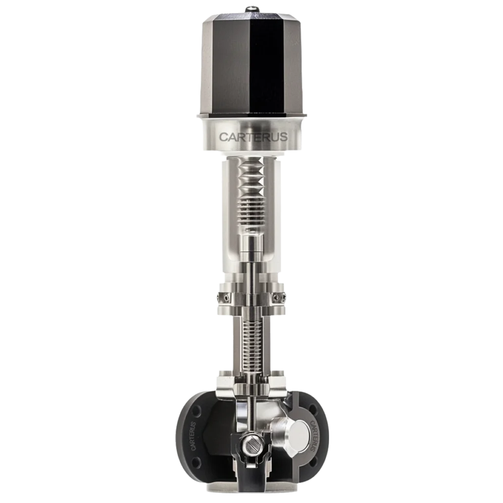
For cavitation, the most effective mechanical solution is the use of anti-cavitation valve trim. This specialized trim forces the fluid through a series of tortuous paths, breaking the massive pressure drop into several smaller, manageable steps. By ensuring that the pressure at each stage remains above the vapor pressure, the trim physically prevents the bubbles from forming.
However, engineers must know when NOT to use anti-cavitation trims. In dirty fluid applications or systems with high particulate counts, the small drilled holes in the multi-stage trim will quickly clog, rendering the valve inoperable. In these cases, engineers must rely on extremely hard alloys, such as Stellite 6, which are required when the Sigma index drops below 1.7.
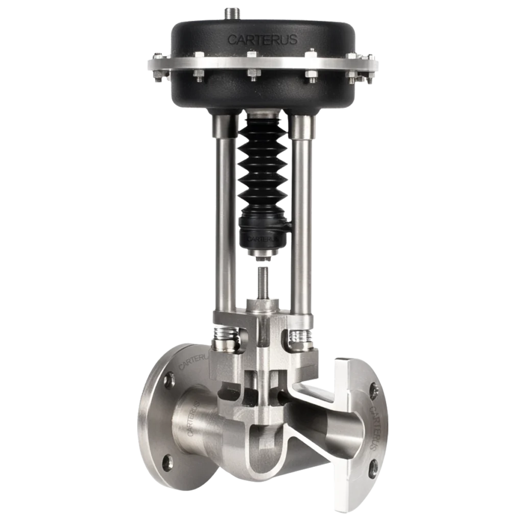
For flashing, anti-cavitation trim is completely ineffective. Because the downstream pressure must remain low, the fluid will always flash. The only solution is to manage the high velocity. Engineers specify angle-style valve bodies that direct the flashing fluid straight down into the piping, preventing it from impinging on the valve walls. Hardened trim materials and oversized downstream piping are also essential to withstand the erosive two-phase flow. These specialized designs are critical in power and energy applications handling boiler blowdown.
What Makes CARTER Control Valve Different
Carter Valve engineers severe service control solutions designed specifically to survive destructive fluid dynamics. Our multi-stage anti-cavitation trims are mathematically modeled to eliminate vapor bubble formation in high-pressure-drop applications, ensuring long-term stability and protecting your piping infrastructure from catastrophic vibration.
We utilize advanced hardened alloys, including solid Stellite and custom heat-treated 440C stainless steel, to provide maximum erosion resistance against both cavitation and flashing. Every severe service ANSI control valve we manufacture guarantees a 98% set pressure tight shut-off and is fully API 526 compliant. Whether you are dealing with a noisy boiler feedwater valve or a failing pressure letdown station, our severe service capabilities ensure your process remains online and safe.
If you are experiencing gravel-like noise or severe vibration in your piping system, you are likely dealing with advanced cavitation. To learn more about our foundational technologies, review our guide on what is a control valve. For safety-critical applications, review our ESD valve selection guide.
For a comprehensive system analysis and custom trim sizing, please visit our contact page to speak with a Carter applications engineer.