


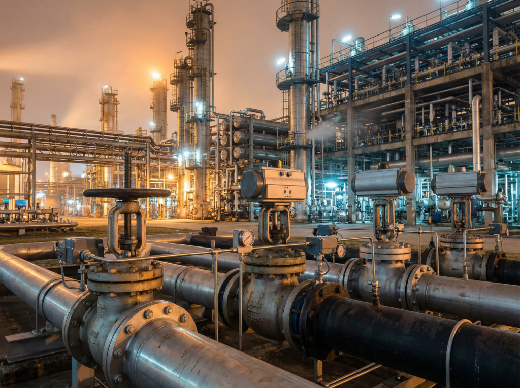
تعتمد حلقات العمليات الصناعية على التنظيم الدقيق للحفاظ على جودة المنتج وسلامة النظام. عندما يرتفع الضغط، أو تنحرف درجات الحرارة، أو تتقلب معدلات التدفق، تكون العملية بأكملها في خطر. التدخل اليدوي مستحيل في العمليات المستمرة الحديثة عالية السرعة.
ويحدث عدم الاستقرار هذا عندما يفتقر النظام إلى طريقة موثوقة لترجمة إشارات التحكم الإلكترونية إلى عمل ميكانيكي مادي. فبدون وجود عنصر تحكم نهائي يمكنه تعديل تدفق البخار أو الغاز أو السائل بشكل فوري ودقيق، فإن أذكى نظام تحكم في العالم يكون مشلولاً بشكل فعال.
يعمل صمام التحكم على حل هذه المشكلة من خلال العمل كـ “الأيدي” المادية لنظام الأتمتة. ومن خلال ضبط حجم ممر التدفق تلقائيًا استنادًا إلى البيانات في الوقت الحقيقي، فإنه يضمن بقاء متغيرات العملية مقفلة على نقاط الضبط الخاصة بها، مما يلغي التخمين اليدوي ويحقق استقرار العملية بأكملها.
جدول المحتويات
ما هو صمام التحكم؟
صمام التحكم هو جهاز يعمل بالطاقة يستخدم لتنظيم تدفق السوائل، مثل الغاز أو الزيت أو الماء أو البخار، داخل نظام معالجة. وهو عنصر التحكم النهائي في نظام الحلقة المغلقة، حيث يتلقى إشارات من وحدة تحكم (مثل PLC أو نظام التحكم المنطقي القابل للبرمجة (DCS)) لتعديل ممر التدفق باستمرار، وبالتالي الحفاظ على التحكم الدقيق في الضغط أو درجة الحرارة أو مستوى السائل أو معدل التدفق.
كيفية عمل صمام التحكم في حلقة العملية
لفهم كيفية عمل صمام التحكم، يجب أن تنظر إلى حلقة التحكم بأكملها. فالصمام لا يعمل بمعزل عن غيره. فهو يعتمد على دورة تغذية مرتدة مستمرة تتضمن ثلاثة مكونات أساسية: المستشعر، وجهاز التحكم، والصمام نفسه.
تبدأ العملية بجهاز استشعار أو جهاز إرسال يقيس متغيرًا معينًا في خط الأنابيب، مثل الضغط في المصب أو درجة حرارة السائل. يرسل هذا المستشعر البيانات في الوقت الفعلي إلى وحدة تحكم مركزية. تعمل وحدة التحكم كعقل للعملية، حيث تقوم بمقارنة القيمة الفعلية المقاسة بالقيمة المستهدفة المطلوبة، والمعروفة باسم نقطة الضبط.
إذا كان هناك انحراف بين القيمة الفعلية ونقطة الضبط، تقوم وحدة التحكم بحساب التصحيح اللازم باستخدام خوارزمية PID (خوارزمية المشتق التناسبي-المتساوي-التدريجي-المشتق). ثم ترسل إشارة خرج - عادةً إشارة كهربائية 4-20 مللي أمبير - إلى صمام التحكم.
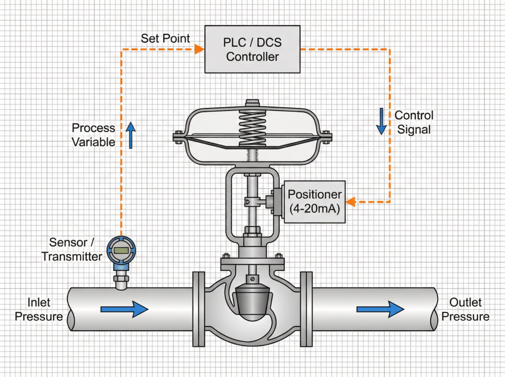
عندما تصل الإشارة إلى الصمام، يقوم جهاز يسمى جهاز تحديد الموضع بتحويل الإشارة الكهربائية إلى خرج هوائي. يقوم هذا الضغط الهوائي بتشغيل المشغل، والذي يحرك جذع الصمام والسدادة فيزيائياً. ومع اقتراب السدادة من مقعد الصمام أو ابتعادها عنه، تتغير مساحة المقطع العرضي لممر التدفق. يغير هذا التعديل الميكانيكي مباشرةً معدل التدفق، مما يعيد متغير العملية إلى نقطة الضبط الدقيقة.
المكونات الرئيسية لمجموعة صمام التحكم
مجموعة صمامات التحكم الكاملة هي أكثر من مجرد قطعة من الأنابيب مع سدادة. إنها وحدة متكاملة تتكون من ثلاثة أنظمة فرعية متميزة.
جسم الصمام هو حد الضغط الأساسي الذي يحتوي على السائل. ويضم مكونات القطع الداخلية، والتي تشمل المقعد، والسدادة (أو القرص)، والساق. والحافة هي المسؤولة عن الاختناق المادي الفعلي للسائل. وتحدد تصميمات الحواف المختلفة خصائص تدفق الصمام، مثل الملامح الخطية أو النسبة المئوية المتساوية أو سريعة الفتح.
يوفر المشغل القوة الميكانيكية المطلوبة لتحريك ساق الصمام. بينما توجد المشغلات الهيدروليكية والكهربائية، فإن المشغِّل الغشائي الهوائي يظل معيار الصناعة نظرًا لموثوقيته ووقت استجابته السريع وقدراته الآمنة من الأعطال. من خلال استخدام الهواء المضغوط ضد غشاء مرن، يمكن للمشغل توليد قوة دفع هائلة للتغلب على ضغوط النظام العالية.
يعمل جهاز تحديد الموضع كجسر اتصال بين وحدة التحكم الإلكترونية والمشغل الهوائي. A جهاز تحديد موضع الصمام الكهربائي الهوائي الرقمي يستقبل إشارة 4-20 مللي أمبير، ويقيس الموضع المادي الفعلي لساق الصمام، ويضبط ضغط الهواء بدقة على المشغِّل حتى يصل الصمام إلى الموضع المطلوب بدقة، مما يزيل الأخطاء الناتجة عن الاحتكاك مثل التباطؤ.
4 أنواع رئيسية من صمامات التحكم
يصنف المهندسون صمامات التحكم حسب حركتها الميكانيكية: الخطية (الجذعية المنزلقة) والدوارة (ربع دورة). ويعتمد الاختيار بالكامل على متطلبات العملية.
1. صمامات التحكم الكروية (خطية)
الصمامات الكروية هي العمود الفقري لصناعة المعالجة. يدخل السائل إلى جسم الصمام، ويقوم بدوران 90 درجة للمرور عبر المقعد، ثم يقوم بدوران آخر بزاوية 90 درجة للخروج. يسمح هذا المسار المتعرج بدقة خنق استثنائية وقدرات انخفاض الضغط العالي. A صمام التحكم في الكرة الأرضية للأغراض العامة هو الخيار الافتراضي لتنظيم التدفق الدقيق. للتطبيقات القصوى التي تنطوي على التجويف أو الوميض، يحدد المهندسون صمام تحكم ANSI للخدمة القاسية مع زخرفة متخصصة مضادة للتجويف.
2. صمامات التحكم بالفراشة (دوارة)
تستخدم صمامات الفراشة قرص دوار للتحكم في التدفق. وهي مفضلة بشدة لخطوط الأنابيب ذات القطر الكبير لأنها مدمجة وخفيفة الوزن وفعالة من حيث التكلفة. في حين أن صمامات الفراشة التقليدية المبطنة بالمطاط مناسبة فقط لخدمة المياه منخفضة الضغط، فإن تصميمات الإزاحة المزدوجة والإزاحة الثلاثية عالية الأداء توفر تحكمًا ممتازًا في التعديل وإغلاقًا محكمًا في تطبيقات الغاز أو البخار ذات درجة الحرارة العالية والضغط العالي.
3. صمامات التحكم الكروية ذات المنفذ الخامس (الدوارة)
صمام كروي قياسي كامل المنفذ مصمم لعزل التشغيل/إيقاف التشغيل، وليس للتحكم الدقيق. ومع ذلك، يتميز الصمام الكروي ذو المنفذ على شكل حرف V بكرة متخصصة مع شق على شكل حرف V مقطوع فيه. أثناء دوران الكرة، تفتح الشق الكروي على شكل حرف V تدريجيًا، مما يوفر خاصية تدفق بنسبة مئوية متساوية. توفر هذه الصمامات سعة تدفق عالية جدًا (Cv عالية) وهي ممتازة للتعامل مع الملاط الليفي أو اللب، حيث أن الشق على شكل V يقص المواد الصلبة العالقة.
4. صمامات تحكم ثلاثية الاتجاهات (خطية)
عندما تتطلب العملية مزج تيارين مائعين معًا أو تقسيم تيار واحد إلى اتجاهين مختلفين، فإن صمام التحكم في الخلط والتحويل ثلاثي الاتجاهات مطلوبة. تُستخدم هذه بكثافة في حلقات التحكم في درجة حرارة المبادل الحراري، حيث يتم تجاوز مياه التبريد حول المبادل الحراري للحفاظ على درجة حرارة المخرج الدقيقة.
الكرة الأرضية مقابل الفراشة مقابل الكرة: مقارنة بين الاختيارات
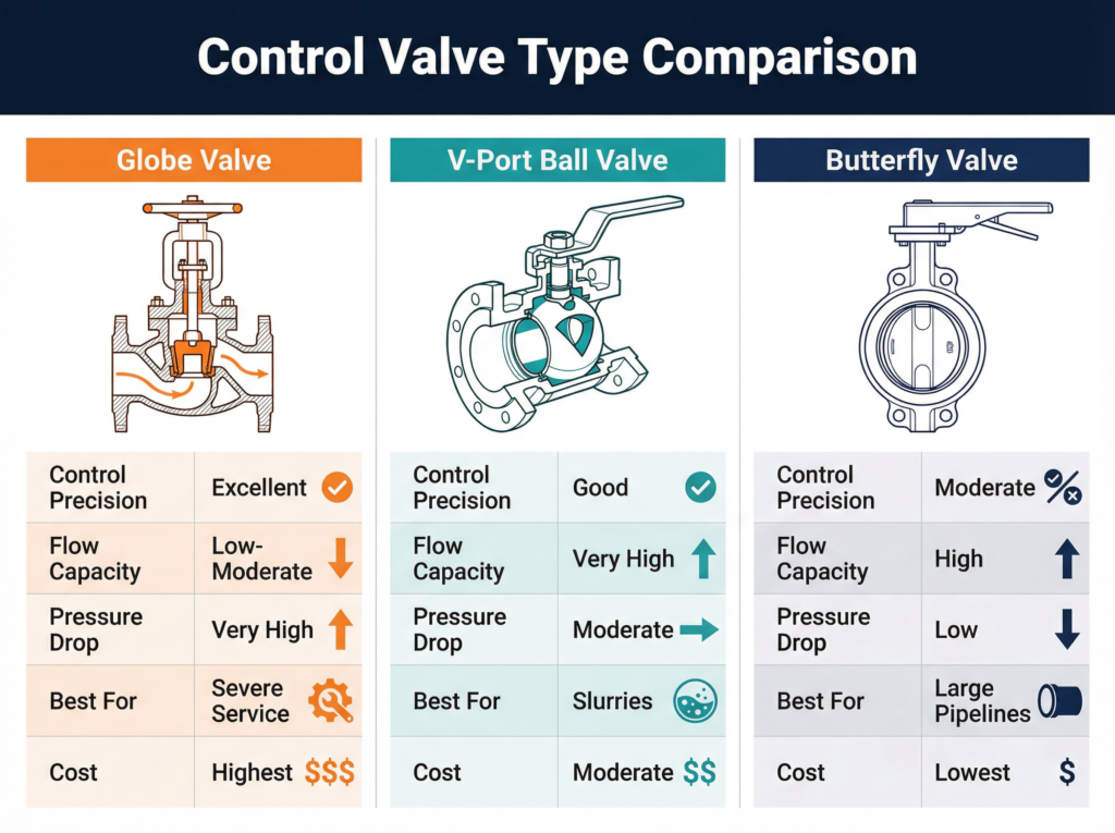
يتطلب اختيار صمام التحكم المناسب الموازنة بين الدقة والسعة والتكلفة. يوضح الجدول أدناه المفاضلات الأساسية.
| الميزة | صمام التحكم في الكرة الأرضية | صمام كروي ذو منفذ على شكل حرف V | صمام تحكم الفراشة |
| نوع الحركة | خطي (جذع منزلق) | دوّار (ربع دورة) | دوّار (ربع دورة) |
| دقة التحكم | ممتاز (أعلى دقة) | جيد (قابلية عالية للمدى) | معتدل (الأفضل بين 20 درجة -70 درجة مئوية) |
| سعة التدفق (Cv) | منخفضة إلى متوسطة | عالية جداً | عالية |
| تحمل انخفاض الضغط | عالية جداً (متوفرة مضادة للتجويف) | معتدل | منخفضة إلى متوسطة |
| أفضل تطبيق | خدمة شديدة، دقة عالية | الطين، سعة التدفق العالي | خطوط الأنابيب الكبيرة، وضيق المساحة |
| التكلفة | الأعلى | معتدل | الأقل |
أحد الأخطاء الشائعة في المواصفات هو استخدام صمام الفراشة للاختناق عالي الضغط. يسبب الاضطراب الناتج اهتزازًا شديدًا وتآكلًا مبكرًا. وعلى العكس من ذلك، فإن استخدام صمام كروي ضخم لخط مياه منخفض الضغط وعالي الحجم يعد تكلفة رأسمالية غير ضرورية.
أوضاع تعطل صمام التحكم الشائعة
حتى أكثرها قوة مجموعة منتجات صمامات التحكم عرضة للفشل إذا تم تحديدها أو صيانتها بشكل غير صحيح. يجب على المهندسين توقع أنماط الفشل الثلاثة الشائعة هذه.
تسرب المقعد وسحب الأسلاك: عندما يعمل الصمام قريبًا جدًا من موضع الإغلاق تحت انخفاضات الضغط العالية، تتسبب نفاثات السوائل عالية السرعة في تآكل المقعد المعدني والسدادة. هذه الظاهرة، المعروفة باسم السحب السلكي، تدمر قدرة الصمام على الإغلاق بإحكام. والحل هو التحجيم المناسب لمقياس Cv لضمان أن يكون الصمام في نطاقه المتوسط الأمثل، أو الترقية إلى حافة ستالايت مقواة.
تسربات التعبئة الجذعية: تعمل التعبئة على إحكام غلق الحركة الديناميكية لساق الصمام ضد ضغط السائل الداخلي. بمرور الوقت، يؤدي التدوير الحراري والاحتكاك إلى تدهور مادة التعبئة، مما يؤدي إلى انبعاثات هاربة. الصيانة الدورية واستخدام أنظمة التعبئة المصنوعة من مادة PTFE أو الجرافيت المحملة مباشرةً مطلوبة لمنع المخاطر البيئية ومخاطر السلامة.
إجهاد نابض المشغل: في التصميمات الآمنة من الفشل، يجبر الزنبرك الداخلي الثقيل الصمام على وضع الإغلاق أو الفتح عند فقدان إمداد الهواء. يمكن أن تتسبب ملايين الدورات في فقدان هذا الزنبرك للشد أو الكسر. يعد الاختبار الروتيني للشوط والصيانة التنبؤية من خلال تشخيصات الموضع الرقمية أمرًا ضروريًا لضمان استجابة الصمام بشكل صحيح أثناء الطوارئ.
سيناريوهات التطبيق حسب الصناعة
يتم تطبيق صمامات التحكم بشكل مختلف اعتمادًا على وسائط السوائل ومتطلبات الصناعة.
في حلول التحكم في تدفق النفط والغاز, ، يجب أن تتعامل الصمامات مع السوائل متعددة الأطوار، والغاز الحامض (H2S)، والضغوط الشديدة. تعتبر مواد مثل الفولاذ المقاوم للصدأ المزدوج والحواف المتوافقة مع NACE إلزامية لمنع التشقق الإجهادي للكبريتيد.
بالنسبة لـ حلول التحكم في العمليات الكيميائية, ، فإن الشاغل الرئيسي هو التآكل والانبعاثات الهاربة. وتتطلب الصمامات التي تتعامل مع المواد الكيميائية القاتلة أغطية مانعة للتسرب منفاخية لضمان عدم وجود تسرب خارجي، وغالبًا ما تكون الأجسام مصبوبة من Hastelloy أو مبطنة بمادة PTFE.
في تطبيقات الطاقة والطاقة, ،مياه تغذية الغلايات ومحطات تفريغ البخار تُعرِّض الصمامات لانخفاضات ضغط هائلة ودرجات حرارة تتجاوز 1,000 درجة فهرنهايت (537 درجة مئوية). يلزم وجود صمامات كروية متعددة المراحل مضادة للتجويف لمنع السائل من تدمير القطع الداخلية من خلال موجات صدمة التجويف.
ما الذي يجعل كارتر مختلفاً
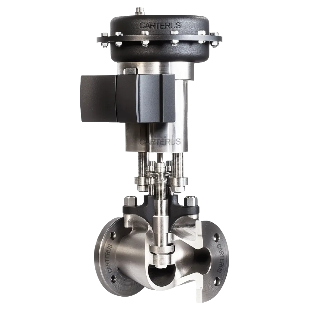
تقوم شركة Carter Technologies بتصنيع مجموعة شاملة من صمامات التحكم في الخدمة الشاقة وصمامات التحكم للأغراض العامة المصممة لبيئات العمليات الأكثر تطلبًا. تعطي تصميماتنا الأولوية للاستقرار على المدى الطويل، وذلك باستخدام مواد توجيه الجذع للخدمة الشاقة ومواد الزخرفة المقواة للتخلص من الاهتزازات وسحب الأسلاك.
نحن نضمن الامتثال المحكم للإغلاق ودقة تحكم استثنائية عبر مجموعتنا الكاملة. وسواء كنت تستبدل صمامًا معطوبًا في خط كيميائي متآكل أو تصمم محطة جديدة لتفريغ البخار عالي الضغط، فإن صماماتنا تمنع العواقب الوخيمة المترتبة على زيادة الحجم وتقلل بشكل كبير من وقت تعطل الصيانة. نحن نقدم خدمة استثنائية وحلولاً هندسية استثنائية، ونعمل باستمرار على توسيع قدراتنا لتلبية متطلبات السوق المتطورة.
إذا كنت تعمل من خلال عملية حسابية معقدة لتحديد الحجم أو كنت تعاني من التجويف في تركيب موجود، فإن فريقنا متاح لمراجعة بيانات العملية الخاصة بك والتوصية بالتكوين المناسب. استكشف تقنياتنا ذات الصلة، مثل صمام تخفيض الضغط المباشر المفعول أو تعرف على صمام يعمل بشكل تجريبي بدائل لمهام محددة لتنظيم الضغط. بالنسبة لأنظمة السلامة الحرجة، راجع دليل اختيار صمام ESD.
للحصول على استشارة فنية مفصلة, اتصل بفريقنا الهندسي اليوم.
توفر شركة كارتر للصمامات حلولاً مصممة هندسيًا للتحكم في التدفق لتطبيقات النفط والغاز والكيماويات والطاقة والعمليات الصناعية. فريقنا الهندسي متاح للاستشارات الفنية بشأن اختيار الصمامات وتحديد أحجامها ومواصفاتها.